Method for Providing Inductively Coupled Radio Frequency Identification (RFID) Transponder, and RFID Transponder

a technology of inductive coupling and radio frequency identification, applied in the field of radio frequency identification (rfid) transponders, can solve the problems of inability to subsequently alter conventional ferrite cores, undesirable attenuation, and no longer available rfid transponders, and achieve the effect of simplifying mechanical construction

Inactive Publication Date: 2012-03-15
SIEMENS AG
View PDF6 Cites 2 Cited by
  • Summary
  • Abstract
  • Description
  • Claims
  • Application Information

AI Technical Summary

Benefits of technology

[0009]It is therefore an object of the present invention to provide a method for simplifying the mechanical construction of a radio frequency identification (RFID) transponder.

Problems solved by technology

However, this is problematic in cases in which the RFID transponder is operated on a metallic surface or in a depression or in a hole in a metallic workpiece.
In these cases, often a large portion of the magnetic flux is conducted through the metallic workpiece and laterally past the transmitting and receiving coil (or simply coil), where the energy of the alternating magnetic field is largely converted into heat by eddy current losses and is therefore no longer available for supplying the RFID transponder.
Conversely, the emissions of the RFID transponder in the case of an arrangement on a metallic workpiece are also largely conducted directly into the metallic workpiece, such that an undesirable attenuation can likewise be observed.
Alongside the resultant expenditure during assembly, it is disadvantageous that the conventional ferrite cores consist of brittle material and therefore cannot subsequently be altered, for example, by machining, etc., by a user, i.e., a manufacturer of RFID transponders, which user / manufacturer generally does not undertake the manufacture of the ferrite cores.
Therefore, mechanical changes to the layout of the RFID transponder are not possible in a straightforward manner.

Method used


Image

  • Method for Providing Inductively Coupled Radio Frequency Identification (RFID) Transponder, and RFID Transponder
  • Method for Providing Inductively Coupled Radio Frequency Identification (RFID) Transponder, and RFID Transponder
  • Method for Providing Inductively Coupled Radio Frequency Identification (RFID) Transponder, and RFID Transponder

Examples


Embodiment Construction

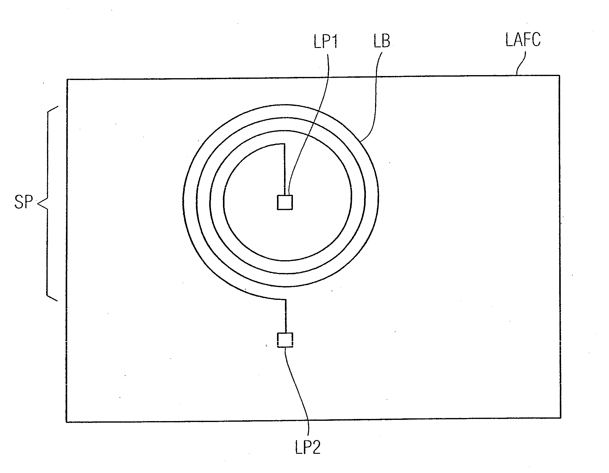
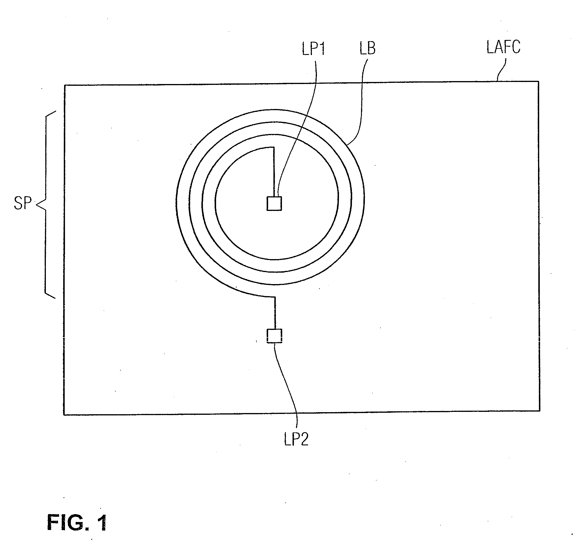
[0019]FIG. 1 is schematic illustration of a ferrite component laser-activated ferrite compound (LAFC) which consists of a liquid crystal polymer (LCP) and which is furnished in a laser-activateable manner. That is, a laser beam can be used to trace lines and areas on the surface of the ferrite component LAFC, thus resulting in a change in the surface constitution in regions processed by the laser light. In addition, it should be noted that a modified polymer is present in these processed regions. This method is known as laser direct patterning (LDP). The present inventors have determined that the modified liquid crystal polymer, which is therefore furnished with an additive for the laser activateability, can be enriched with ferrite particles, without the insulating properties (electrical insulation) and the laser activateability being impaired. The ferrite component LAFC shown here includes a laser-activateable plastic enriched with ferrite particles in this way, where, with the us...


PUM

PropertyMeasurementUnit
magnetic fluxaaaaaaaaaa
magnetic fieldaaaaaaaaaa
AC voltageaaaaaaaaaa

Abstract

A radio frequency identification (RFID) transponder for use in an RFID arrangement with inductive coupling, where interaction of a transmitting and receiving coil with a ferrite component is provided for guiding the magnetic flux. Here, the ferrite component for guiding the magnetic flux includes a composite material comprising a plastic and ferrite powder, where the plastic is furnished in a laser-patternable manner, such that the transmitting and receiving coil is formed by at least one conductor track and then precontoured by laser processing metalized in or on a surface of the component. Such an RFID transponder is robust, easy and simple to produce.

Description

BACKGROUND OF THE INVENTION[0001]1. Field of the Invention[0002]The invention relates to radio frequency identification (RFID) transponders, and more particularly, to an RFID transponder, and a method for producing the RFID transponder.[0003]2. Description of the Related Art[0004]Mobile data memories that can be read contactlessly are often used for identifying goods, machines and other articles. In this case, optically readable barcode labels are increasingly being replaced by electromagnetically or magnetically writeable and readable radio frequency identification (RFID) labels, i.e., RFID transponders. In a preferred configurations, the RFID transponders operate without a dedicated power supply, such as a battery.[0005]Different technologies are used in RFID transponders depending on the case of use. Thus, for labeling garments and other far field applications, for example, the RFID transponders are coupled to the reader by radio, i.e., by electromagnetic waves. However, inductiv...

Claims


Application Information

Patent Timeline
Patent Type & Authority Applications(United States)
IPC IPC(8): G06K19/077H01P11/00
CPCG06K19/07749Y10T29/49016G06K19/07771H05K1/0373H05K3/0014H05K3/105H05K2201/0129H05K2201/083H05K2201/09118H05K2203/107
Inventor KUBE, ROLANDBERND, STADELMANN
Owner SIEMENS AG
Why Eureka
Try Eureka