Microplasma source and sterilization system including the same

a technology of sterilization system and microplasma, which is applied in the direction of plasma technique, disinfection, energy-based chemical/physical/physico-chemical process, etc., can solve the problems of limiting the use of the above mentioned dbd plasma, affecting the sterilization effect of the sterilization system, so as to achieve the effect of not needing high power consumption and low power consumption

Active Publication Date: 2012-03-15
NAT CHENG KUNG UNIV
View PDF3 Cites 26 Cited by
  • Summary
  • Abstract
  • Description
  • Claims
  • Application Information

AI Technical Summary

Benefits of technology

[0008]The object of the present invention is to provide a microplasma source, which does not need high power consumption and can be minimized into a pen size. In this microplasma source, a hollow inner electrode is employed and the reactive and plasma maintenance gases are supplied in

Problems solved by technology

However, currently known sterilization methods such as dry autoclave process, the treatment of chemical bactericide such as ethylene oxide, and physical irradiation will result in different degrees of degradation or damage to the treated surfaces.
Nevertheless, there are limits in the use of the above mentioned DBD plasma because most medical apparatus have irregular shapes, and it is difficult for the DBD pl

Method used


Image

  • Microplasma source and sterilization system including the same
  • Microplasma source and sterilization system including the same
  • Microplasma source and sterilization system including the same

Examples


example 1

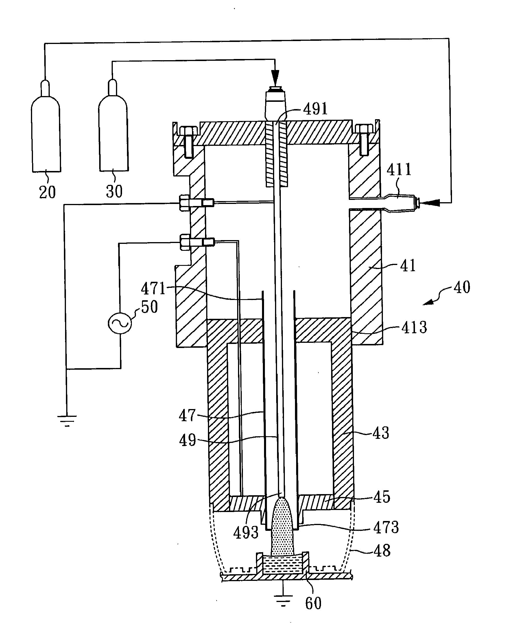
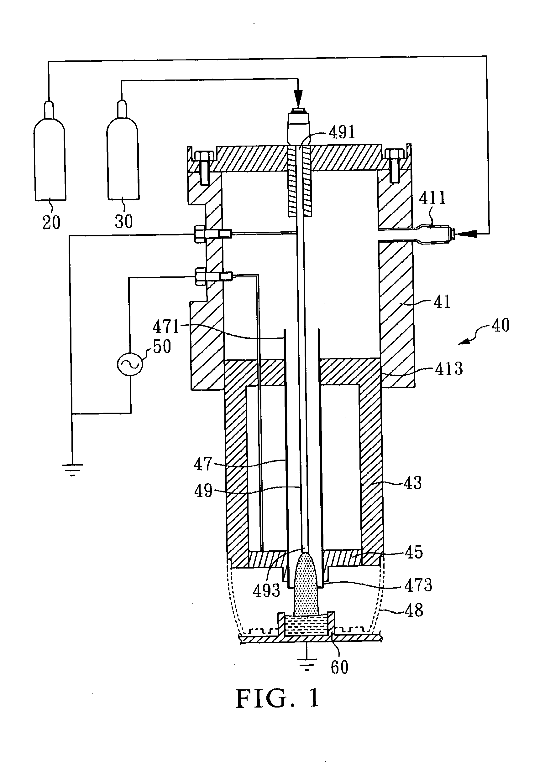
[0030]FIG. 1 is a perspective view of the microplasma source in the present example. As shown in FIG. 1, the microplasma source 10 of the present invention mainly includes: a first gas storage unit 20, a second gas storage unit 30, a microplasma-generating unit 40, and a power supply unit 50.

[0031]In the present invention, the first gas storage unit 20 is used for storage of a first gas. Likely, the second gas storage unit 30 is used for storage of a second gas. In the present example, the first gas serves as an excitation gas such as argon, and the second gas serves as a reactive gas such as oxygen.

[0032]In the microplasma-generating unit 40, a gas transmission chamber 41, a protection and heat dissipation chamber 43, a dielectric inner tube 47, an electrode 45, a hollow metal tube 49, and a positioning sleeve 48 are included. The gas transmission chamber 41 has a first inlet 411 and a first outlet 413. In the gas transmission chamber 41, the first inlet 411 is connected to the fir...

example 2

[0035]The microplasma sterilization system of the present example is shown as FIG. 1 and mainly includes: a microplasma source 10, a first gas storage unit 20, a second gas storage unit 30, a microplasma-generating unit 40, and a power supply unit 50. In the present example, the structure of the microplasma sterilization system is substantially the same to that of Example 1. In addition to components delineated above, a sample tank 60 can be further provided to receive a solid or liquid sample if necessary.


PUM


Abstract

A microplasma source and a sterilization system including the same are disclosed. The microplasma source includes: a microplasma-generating unit including: a gas transmission chamber having a first inlet and a first outlet wherein the first inlet is used to import a first gas; a protection and heat dissipation chamber of which a side is connected to the inner wall of the first outlet; a dielectric inner tube having a second inlet and a second outlet and penetrating through the protection and heat dissipation chamber, wherein the second inlet is communicated to the gas transmission chamber; an electrode arranged outside at the second outlet and located in the protection and heat dissipation chamber; and a hollow metal tube disposed in the gas transmission chamber and the dielectric inner tube and having a third inlet and a third outlet, wherein the third inlet is used to import a second gas.

Description

CROSS REFERENCE TO RELATED APPLICATION[0001]This application claims the benefit of filing date of U.S. Provisional Application Ser. No. 61 / 380,419, entitled “Capillary tube based oxygen / argon micro-plasma system for the inactivation / sterilization of bacteria suspended in aqueous solution” filed Sep. 7, 2010 under 35 USC §119(e)(1).BACKGROUND OF THE INVENTION[0002]1. Field of the Invention[0003]The present invention relates to a microplasma source and, more particularly, to a microplasma source and a sterilization system suitable for the sterilization of reusable medical apparatus and furthermore for injured or infected tissues inactivation / sterilization.[0004]2. Description of Related Art[0005]When reusable medical apparatus such as surgical or dental medical devices are sterilized, total elimination of all microorganisms such as bacteria, fungi, or viruses from the apparatus has to be confirmed to prevent any possible infection to a next patient. However, currently known sterilizat...

Claims


Application Information

Patent Timeline
IPC IPC(8): B01J19/08
CPCA61L2/14H05H2245/1225H05H1/48H05H1/2406H05H2245/36
Inventor LIAO, JIUNN-DERWENG, CHIH-CHIANGCHEN, HSING-HUNGLIN, TUNG-YI
Owner NAT CHENG KUNG UNIV
Why Eureka
Try Eureka