
Interconnecting plate for solid oxide fuel cell and manufacturing method thereof, and solid oxide fuel cell using the interconnecting plate

Inactive Publication Date: 2012-03-15
SAMSUNG ELECTRO MECHANICS CO LTD
View PDF2 Cites 6 Cited by
  • Summary
  • Abstract
  • Description
  • Claims
  • Application Information

AI Technical Summary

Benefits of technology

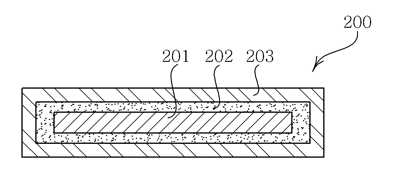
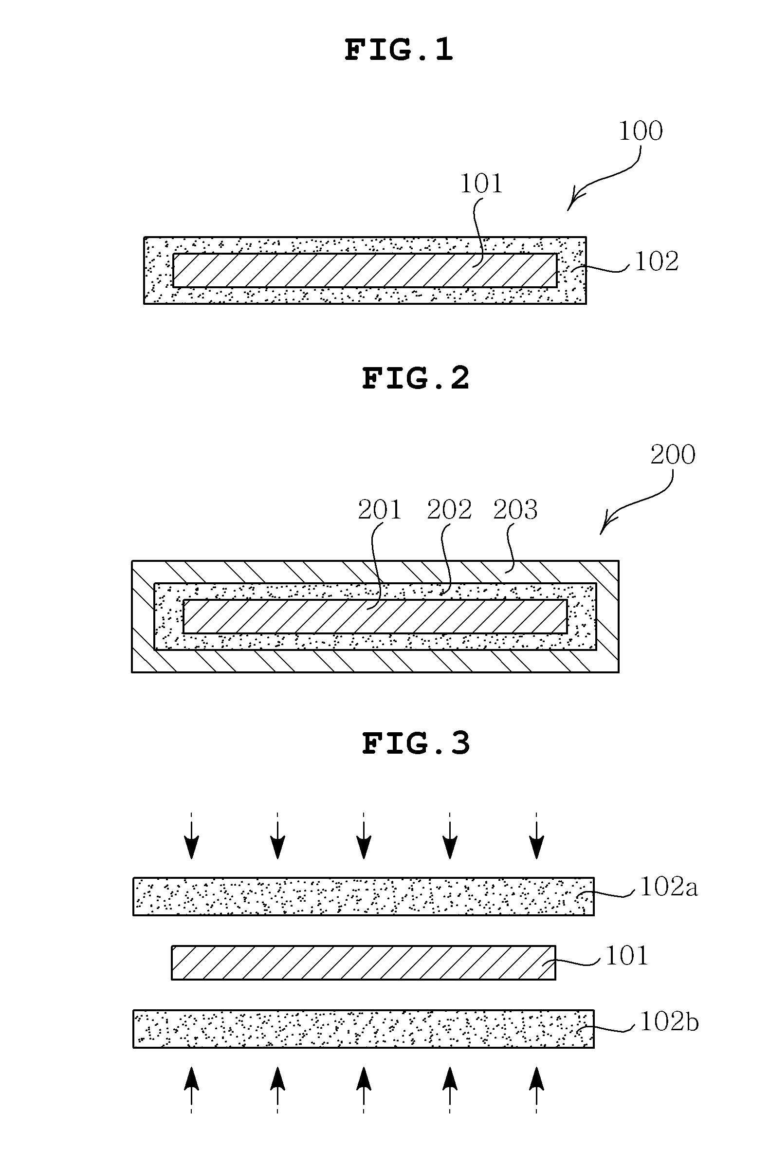
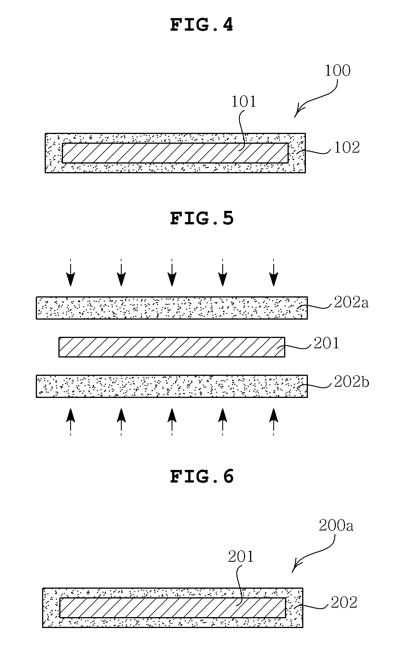
[0015]The present invention has been made in an effort to provide an interconnecting plate for a solid oxide fuel cell capable of improving productivity and saving cost according to process simplification by forming a protective layer for an interconnecting plate using a conductive ceramic sheet and a manufacturing method thereof.
[0016]Further, the present invention has been made in an effort to provide an interconnecting plate for a solid oxide fuel cell capable of improving durability of metal and maintaining excellent electric conductivity under high-temperature oxidation atmosphere by forming a dense protective layer, as compared to the existing method such as the plasma spray or the dip coating, and a manufacturing method thereof.

Problems solved by technology

In this case, it is not easy to accurately control the thickness of the coating layer and in order to obtain the predetermined thickness, the dipping and drying should be performed several times, such that the manufacturing time is long and it is difficult to form the thick coating layer.
Meanwhile, when using the plasma spray is used, since the coating powder is melted and then, is sprayed and coated on the metal plate, there is a problem in that the composition of the final coating layer is different when volatile materials such as Cr are included in the powder component.
Further, since the coating layer is formed by the spraying, there are problems in that the surface of the coating layer is uneven and it is difficult to control the thickness of the coating.
As such, there are problems in that the existing methods, such as dip-coating, plasma-spray, sputter, etc., have a complicated process and consume a great deal of time and cost.

Method used


Image

  • Interconnecting plate for solid oxide fuel cell and manufacturing method thereof, and solid oxide fuel cell using the interconnecting plate
  • Interconnecting plate for solid oxide fuel cell and manufacturing method thereof, and solid oxide fuel cell using the interconnecting plate
  • Interconnecting plate for solid oxide fuel cell and manufacturing method thereof, and solid oxide fuel cell using the interconnecting plate

Examples


Embodiment Construction

[0035]Various features and advantages of the present invention will be more obvious from the following description with reference to the accompanying drawings.

[0036]The terms and words used in the present specification and claims should not be interpreted as being limited to typical meanings or dictionary definitions, but should be interpreted as having meanings and concepts relevant to the technical scope of the present invention based on the rule according to which an inventor can appropriately define the concept of the term to describe most appropriately the best method he or she knows for carrying out the invention.

[0037]The above and other objects, features and advantages of the present invention will be more clearly understood from the following detailed description taken in conjunction with the accompanying drawings. In the specification, in adding reference numerals to components throughout the drawings, it is to be noted that like reference numerals designate like component...


PUM


Abstract

Disclosed herein are an interconnecting plate for a solid oxide fuel cell, a manufacturing method thereof, and a solid oxide fuel cell using the interconnecting plate. The interconnecting plate for a solid oxide fuel cell includes a metal substrate; and a conductive ceramic protective layer surrounding the metal substrate, wherein the ceramic protective layer is formed by disposing and stacking the metal substrate between a pair of ceramic sheets.

Description

CROSS REFERENCE TO RELATED APPLICATION[0001]This application claims the benefit of Korean Patent Application No. 10-2010-0089215, filed on Sep. 13, 2010, entitled “Interconnecting Plate For Solid Oxide Fuel Cell And Manufacturing Method Thereof, And Solid Oxide Fuel Cell Using Said Interconnecting Plate” which is hereby incorporated by reference in its entirety into this application.BACKGROUND OF THE INVENTION[0002]1. Technical Field[0003]The present invention relates to an interconnecting plate for a solid oxide fuel cell, a manufacturing method thereof, and a solid oxide fuel cell using the interconnecting plate.[0004]2. Description of the Related Art[0005]A solid oxide fuel cell is operated at the highest temperature (700 to 1000° C.) among fuel cells using solid oxide having oxygen or hydrogen ion conductivity as an electrolyte and all components of the solid oxide fuel cell are made of solid, such that it has a simpler structure, does not lead to problems, such as the loss, sup...

Claims


Application Information

Patent Timeline
IPC IPC(8): H01M8/12H01M4/04H01M4/66
CPCH01M8/0206H01M8/0215H01M8/0228H01M2008/1293Y02E60/50B32B2457/18B32B9/005B32B9/041B32B3/04B32B2307/202Y02E60/525Y02P70/50
Inventor KOO, BON SEOKYOON, JONG SIKJANG, JAE HYUK
Owner SAMSUNG ELECTRO MECHANICS CO LTD
Features
  • Generate Ideas
  • Intellectual Property
  • Life Sciences
  • Materials
  • Tech Scout
  • Unparalleled Data Quality
  • Higher Quality Content
  • 60% Fewer Hallucinations
Learn More