

Dc-dc converter
a converter and dc technology, applied in the direction of electric variable regulation, process and machine control, instruments, etc., can solve problems such as efficiency reduction, and achieve the effect of reducing not only the turn-off loss but also the turn-on loss
- Summary
- Abstract
- Description
- Claims
- Application Information
AI Technical Summary
Benefits of technology
Problems solved by technology
Method used
Image

Examples
first preferred embodiment
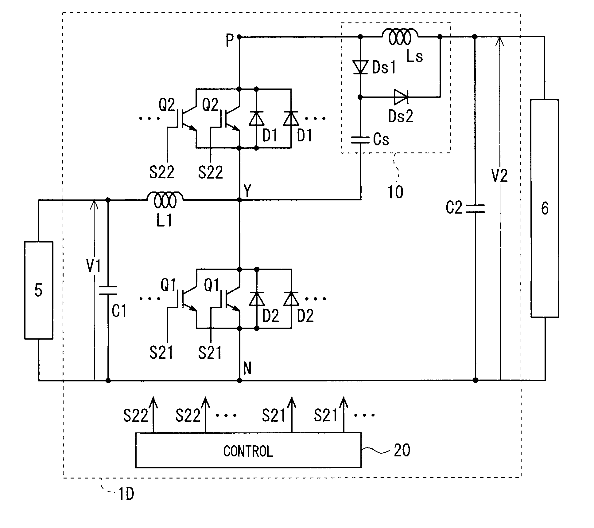
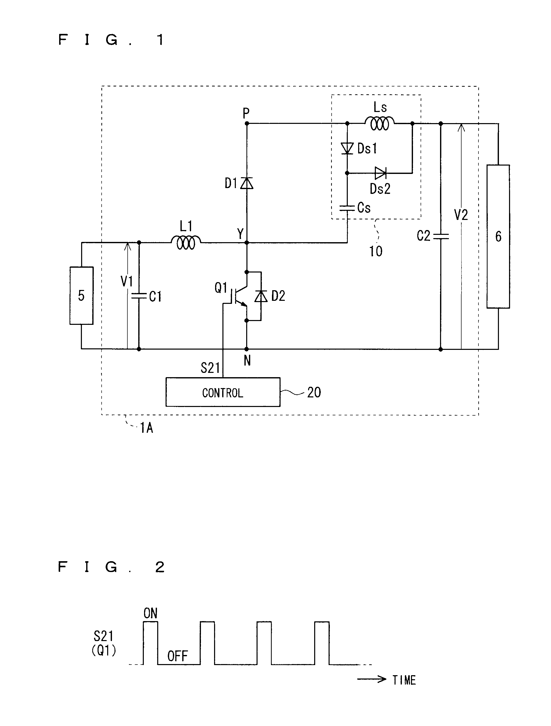
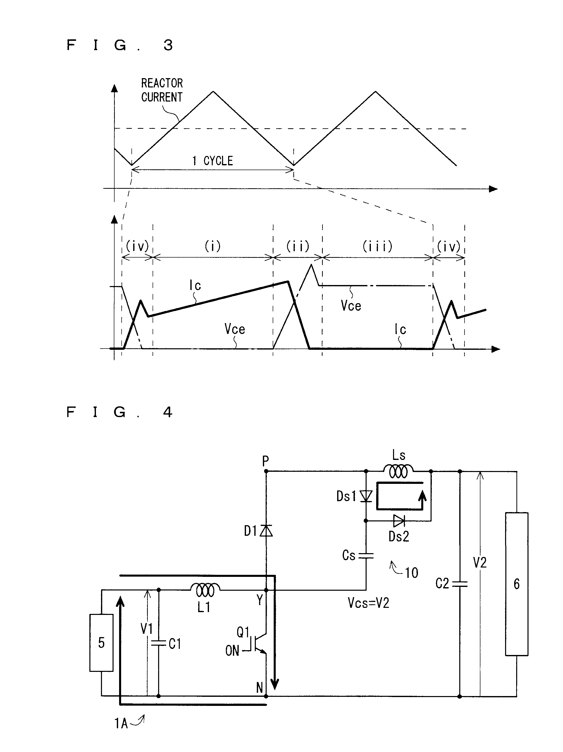
[0033]FIG. 1 shows a circuit diagram schematically showing a configuration of a DC-DC converter (hereinafter, sometimes abbreviated as a converter) 1A according to a first preferred embodiment. As illustrated in FIG. 1, the converter 1A is used by being connected between a low voltage-side device 5 and a high voltage-side device 6. In other words, the low voltage-side device 5 is connected to low voltage-side connection ends of the converter 1A, and the high voltage-side device 6 is connected to high voltage-side connection ends of the converter 1A.
[0034]The converter 1A is a step-up converter, and has a configuration capable of executing a step-up operation in which a voltage V1 on the low voltage-side connection ends is stepped up to a voltage V2 (>V1) and the stepped-up voltage V2 is outputted to the high voltage-side connection ends. In other words, the converter 1A steps up the voltage V1, which is applied thereto by the low voltage-side device 5, to the voltage V2, and supplie...
second preferred embodiment
[0087]FIG. 13 shows a circuit diagram schematically showing a configuration of a converter 1B according to a second preferred embodiment. The converter 1B is a so-called bidirectional step-up / down (also referred to as bidirectional) converter. That is, the converter 1B has a configuration capable of executing both of the step-up operation (the voltage V1 on the low voltage-side connection ends is stepped up to the voltage V2, and the stepped-up voltage V2 is outputted to the high voltage-side connection ends) and a step-down operation (the voltage V2 on the high voltage-side connection ends is stepped down to the voltage V1, and the stepped-down voltage V1 is outputted to the low voltage-side connection ends). In other words, in the step-up operation, the converter 1B steps up the voltage V1, which is applied by the low voltage-side device 5, to the voltage V2, and supplies the stepped-up voltage V2 to the high voltage-side device 6. On the other hand, in the step-down operation, th...
third preferred embodiment
[0122]FIG. 24 shows a circuit diagram schematically showing a configuration of a converter 1C according to a third preferred embodiment. The converter 1C illustrated in FIG. 24 has a configuration in which the step-up transistor Q1 is removed from the bidirectional step-up / down converter 1B (see FIG. 13) according to the second preferred embodiment. That is, the converter 1C is tailored to be step-down. Other configurations of the converter 1C are basically similar to those of the converter 1B. Note that, from a viewpoint of the step-down operation, it is also possible to omit the step-up diode D1.
[0123]Note that, in the third preferred embodiment, the case is illustrated, where the low voltage-side device 5 is a variety of loads or a rechargeable battery, and the high voltage-side device 6 is a DC power supply (which may be a device in which an AC generator and an inverter are combined with each other, and the like).
[0124]In accordance with the converter 1C, in the step-down operat...
PUM
 Abstract
Description
Claims
Application Information