
Coil arrangement

a coil and arrangement technology, applied in the field of coil arrangement, can solve the problems of difficulty in tuning, low signal to noise ratio (snr), and the size of the rf coil to produce a lower signal to noise ratio (snr)

Active Publication Date: 2012-03-22
QUEENSLAND THE UNIV OF
View PDF61 Cites 3 Cited by
  • Summary
  • Abstract
  • Description
  • Claims
  • Application Information

AI Technical Summary

Benefits of technology

[0010]The present invention seeks to substantially overcome, or at least ameliorate, one or more disadvantages of existing arrangements.

Problems solved by technology

However, the large size of this RF coil produces a lower signal to noise ratio (SNR) if it is also used for reception, mainly because of its greater distance from the signal generating tissues being imaged.
A multi-element RF coil array usually suffers from strong mutual coupling between individual coil elements and some of the undesirable effects include difficulty in tuning, reduced SNR and RF field distortion causing image artefacts.
There are some constraints, however, in using these decoupling methods.
The overlapping of adjacent coils sacrifices the area of coverage, lumped-element decoupling networks have limitations on their decoupling power and the use of low input impedance preamplifiers can limit power transfer and limit the use of the phased array coils to receive only (i.e not suitable for transceive operation).

Method used


Image

  • Coil arrangement
  • Coil arrangement
  • Coil arrangement

Examples


Embodiment Construction

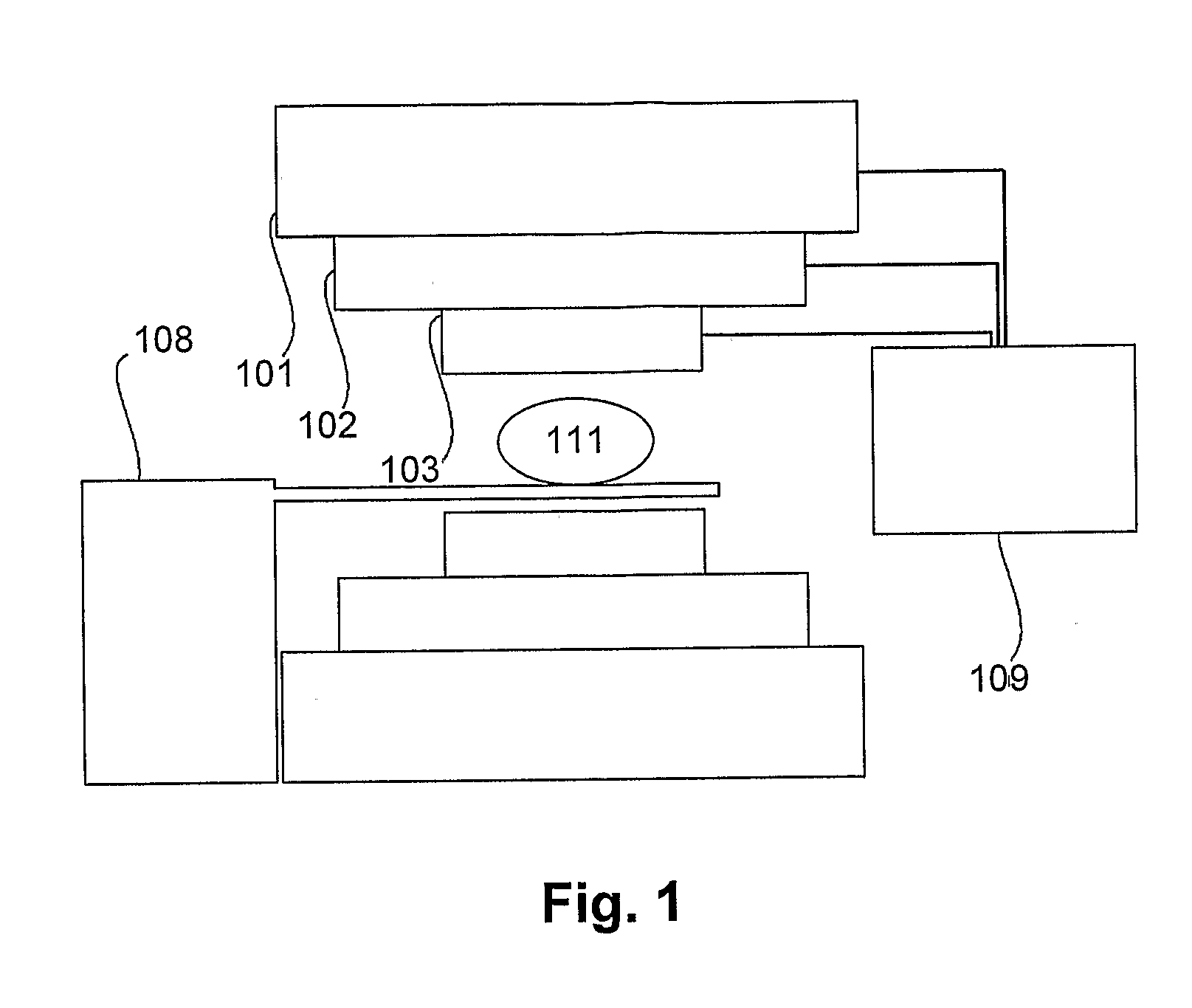
[0081]An example of a magnetic resonance (MR) imaging system will now be described with reference to FIG. 1.

[0082]In this example, the MR system includes a main or primary shimmed magnet 101, three principal axis gradient coils 102, a patient / sample bed 108 and MR instrumentation 109. In use, the main magnet 101 is adapted to generate a substantially homogeneous magnetic field over an imaging region 111, which contains a subject, such as at least part of a patient or sample. The subject is then exposed to an RF field, allowing MRI to be performed. The workings of these components are substantially identical to those of contemporary systems, and will not therefore be described in any further detail.

[0083]The RF field is typically transmitted and received by one or more RF coil arrays 103. In one example, separate coil arrays may be used for transmitting and receiving the RF field, whilst in another example a single transceive coil array could be used.

[0084]An example of a coil array ...


PUM


Abstract

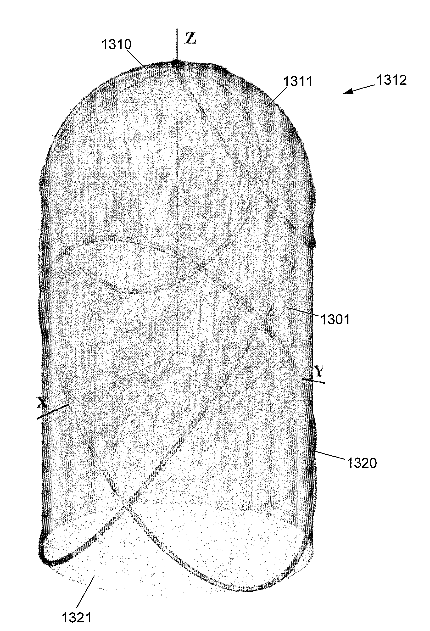
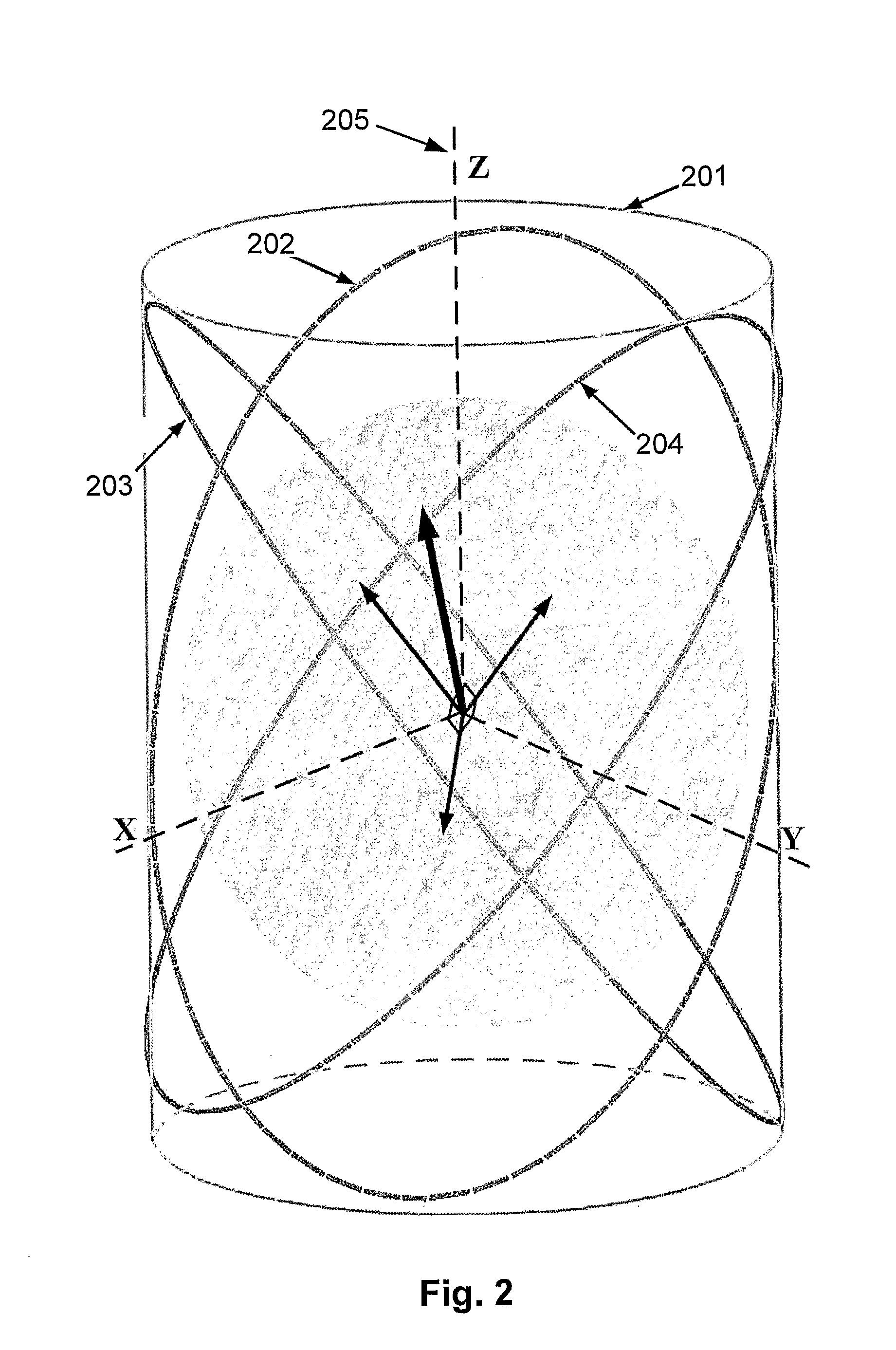
A coil arrangement for use in a magnetic resonance imaging system, the imaging system being for generating a magnetic imaging field in an imaging region, the coil arrangement including at least three coils for at least one of transmitting, receiving or transceiving an electromagnetic field, each coil being provided on a coil geometry and being substantially orthogonal.

Description

BACKGROUND OF THE INVENTION[0001]The present invention relates to a coil arrangement for use in a magnetic resonance imaging system, a method for use in determining a coil arrangement for use in a magnetic resonance imaging system and in particular to a coil arrangement having mutually orthogonal coils.DESCRIPTION OF THE PRIOR ART[0002]The reference in this specification to any prior publication (or information derived from it), or to any matter which is known, is not, and should not be taken as an acknowledgment or admission or any form of suggestion that the prior publication (or information derived from it) or known matter forms part of the common general knowledge in the field of endeavour to which this specification relates.[0003]In MRI, when a substance such as the human tissue is exposed to a strong and uniform polarizing static magnetic field B0, the spins of abundant water hydrogen protons in the tissue align their individual magnetic moments along the magnetic field B0, in...

Claims


Application Information

Patent Timeline
Patent Type & Authority Applications(United States)
IPC IPC(8): G01R33/28
CPCA61B5/055A61B5/4528G01R33/365G01R33/3415A61B5/4533
Inventor CROZIER, STUARTTRAKIC, ADNANWEBER, EWALDLI, BING KEONGWANG, HUA
Owner QUEENSLAND THE UNIV OF
Learn More