Fuel gas supply device of fuel cell system
- Summary
- Abstract
- Description
- Claims
- Application Information
AI Technical Summary
Benefits of technology
Problems solved by technology
Method used
Image
Examples
first embodiment
[0030]With reference to FIGS. 1 to 8, this invention is described.
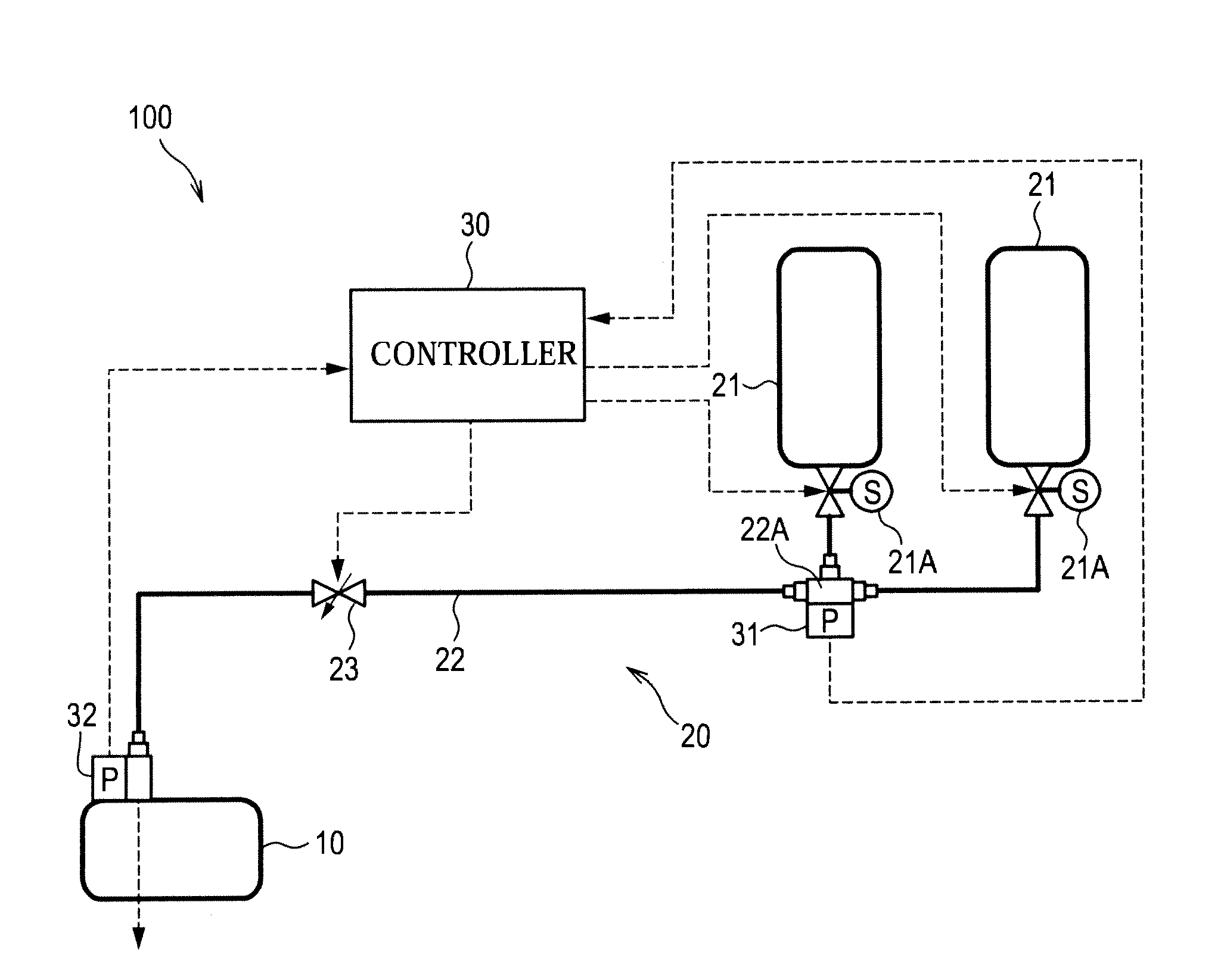
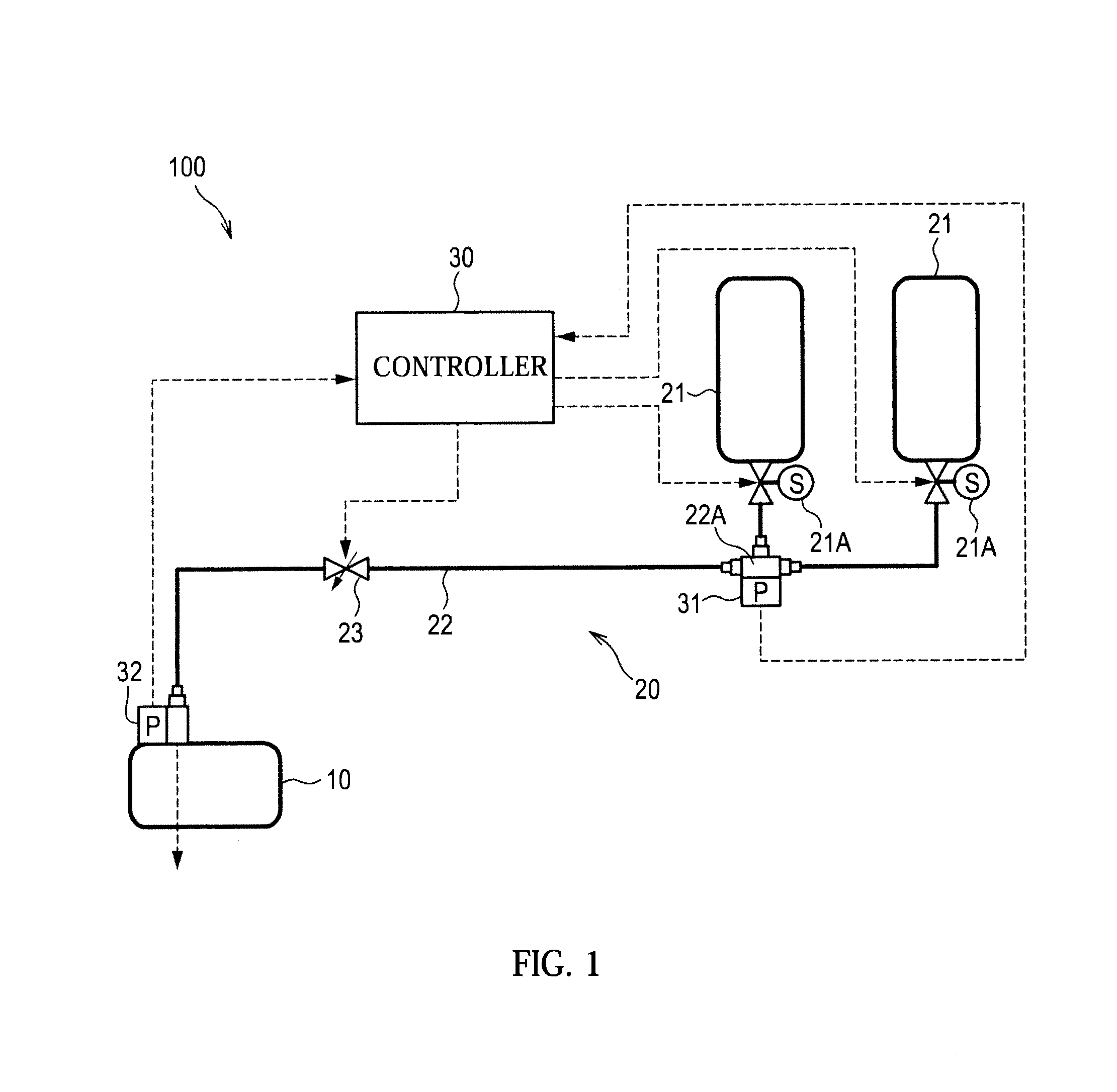
[0031]FIG. 1 is a schematic diagram of a fuel cell system 100 to be mounted in an electric vehicle.
[0032]The fuel cell system 100 includes a fuel cell stack 10 and a hydrogen supply mechanism 20.
[0033]The fuel cell stack 10 is formed by laminating solid polymer unit cells, which generate power using hydrogen as fuel gas supplied by the hydrogen supply mechanism 20 and air as oxidant gas supplied by an unillustrated air supply mechanism, in a plurality of layers. The fuel cell stack 10 generates power necessary to drive the electric vehicle.
[0034]The hydrogen supply mechanism 20 is a means for supplying hydrogen to the fuel cell stack 10 and includes high-pressure hydrogen tanks 21, a hydrogen supply path 22, a hydrogen supply control valve 23 and a controller 30.
[0035]Two high-pressure hydrogen tanks 21 are provided at an upstream side of the hydrogen supply path 22. The high-pressure hydrogen tanks 21 store hydrogen ...
second embodiment
[0061]Next, this invention is described with reference to FIGS. 9 to 11.
[0062]Although a fuel cell system 100 according to the second embodiment has substantially the same construction as the first embodiment, it differs in how to determine a required opening η, an opening time TO and a closing time TC of a hydrogen supply control valve 23.
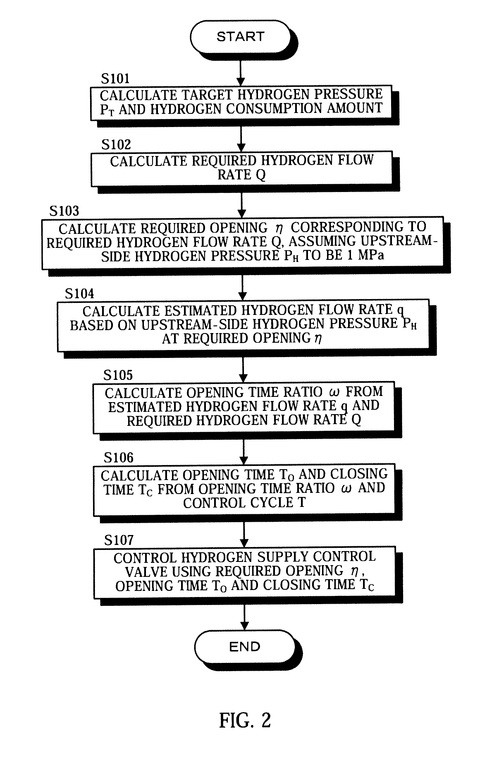
[0063]Referring to FIG. 9, a control routine for the hydrogen supply control valve 23 executed by a controller 30 of the fuel cell system 100 according to the second embodiment is described. Contents of Steps S101, S102 and S107 of FIG. 9 are not described in detail since being similar to Steps S101, S102 and S107 of FIG. 2.
[0064]After calculating a required hydrogen flow rate Q in Step S102, the controller 30 performs the processing of Step S108.
[0065]In Step S108, the controller 30 calculates an opening time ratio ω so that an average flow rate of hydrogen during a control cycle T becomes a required hydrogen flow rate Q, assuming that an upstrea...
third embodiment
[0077]Next, this invention is described with reference to FIGS. 12 and 13.
[0078]Although a fuel cell system 100 according to the third embodiment has substantially the same construction as the first and second embodiments, it differs in that a required opening η, an opening time TO and a closing time TC of a hydrogen supply control valve 23 are corrected according to a vehicle operating state or the like.
[0079]Referring to FIG. 12, a control subroutine for the hydrogen supply control valve 23 executed by a controller 30 according to the third embodiment is described. This subroutine is performed in Step S107 of the first or second embodiment.
[0080]In Step S201, the controller 30 determines whether or not the vehicle is in acceleration based on a deviation between the target hydrogen pressure PT and the downstream-side hydrogen pressure PL.
[0081]If the deviation between the target hydrogen pressure PT and the downstream-side hydrogen pressure PL is large, the controller 30 determines...
PUM
 Abstract
Description
Claims
Application Information
 - R&D
- Intellectual Property
- Life Sciences
- Materials
- Tech Scout
- Unparalleled Data Quality
- Higher Quality Content
- 60% Fewer Hallucinations
Browse by: Latest US Patents, China's latest patents, Technical Efficacy Thesaurus, Application Domain, Technology Topic, Popular Technical Reports.
© 2025 PatSnap. All rights reserved.Legal|Privacy policy|Modern Slavery Act Transparency Statement|Sitemap|About US| Contact US: help@patsnap.com


