Magnetic resonance thermometry using prf spectroscopy

a magnetic resonance and thermometry technology, applied in the field of magnetic resonance thermometry, can solve the problems of compromising the accuracy of temperature determinations based on prf changes, affecting the accuracy of temperature determinations, and sensitive to rapid anatomical phase, so as to achieve the effect of minimizing the error

Inactive Publication Date: 2012-03-22
INSIGHTEC
View PDF1 Cites 43 Cited by
  • Summary
  • Abstract
  • Description
  • Claims
  • Application Information

AI Technical Summary

Benefits of technology

[0013]The computational model need not necessarily serve to biophysically simulate the temperature evolution in tissue. Rather, in some embodiments, the computational model consists of an analytical temperature profile (e.g., a combination of polynomial or other functions) with adjustable coefficients. In accordance with the present invention, the model coefficients are adjusted to fit the profile to the measurements, i.e., to minimize the error between the measured and predicted temperatures.
[0014]Once the computational model has been adjusted based on the temperature measurements in subregions containing (e.g., at interfaces between) fatty and non-fatty tissues or materials, it can be used to compute an absolute-temperature map for the zone of interest. This map may then be used as a temperature baseline in conjunction with conventional PRF-shift thermometry. For example, the temperature change in a focal zone that results from an individual sonication may be determined with traditional reference-based or referenceless thermometry methods, and may be added to a temperature map that reflects the cumulative effect of a series of preceding sonications on the temperature in and surrounding the focal zone, yielding an absolute-temperature map for the entire zone of interest. Supplementing prior PRF techniques with methods according to the present invention can, thus, overcome the time constraints inherent in the prior techniques.

Problems solved by technology

Thus, short-term changes in temperature can be measured accurately using PRF, but when an absolute temperature measurement is needed over a relatively long period of time (i.e., hours), the effect of slow mechanisms will become pronounced and compromise the accuracy of temperature determinations based on PRF changes.
While referenceless methods are immune to motion, they are sensitive to rapid anatomical phase variations, which commonly exist at organ edges, since these cannot be accurately expressed as a weighted sum of smooth functions.
Uncertainties in parameters of the model, such as tissue and blood-flow parameters, can generally result in prediction inaccuracies.

Method used


Image

  • Magnetic resonance thermometry using prf spectroscopy
  • Magnetic resonance thermometry using prf spectroscopy
  • Magnetic resonance thermometry using prf spectroscopy

Examples


Embodiment Construction

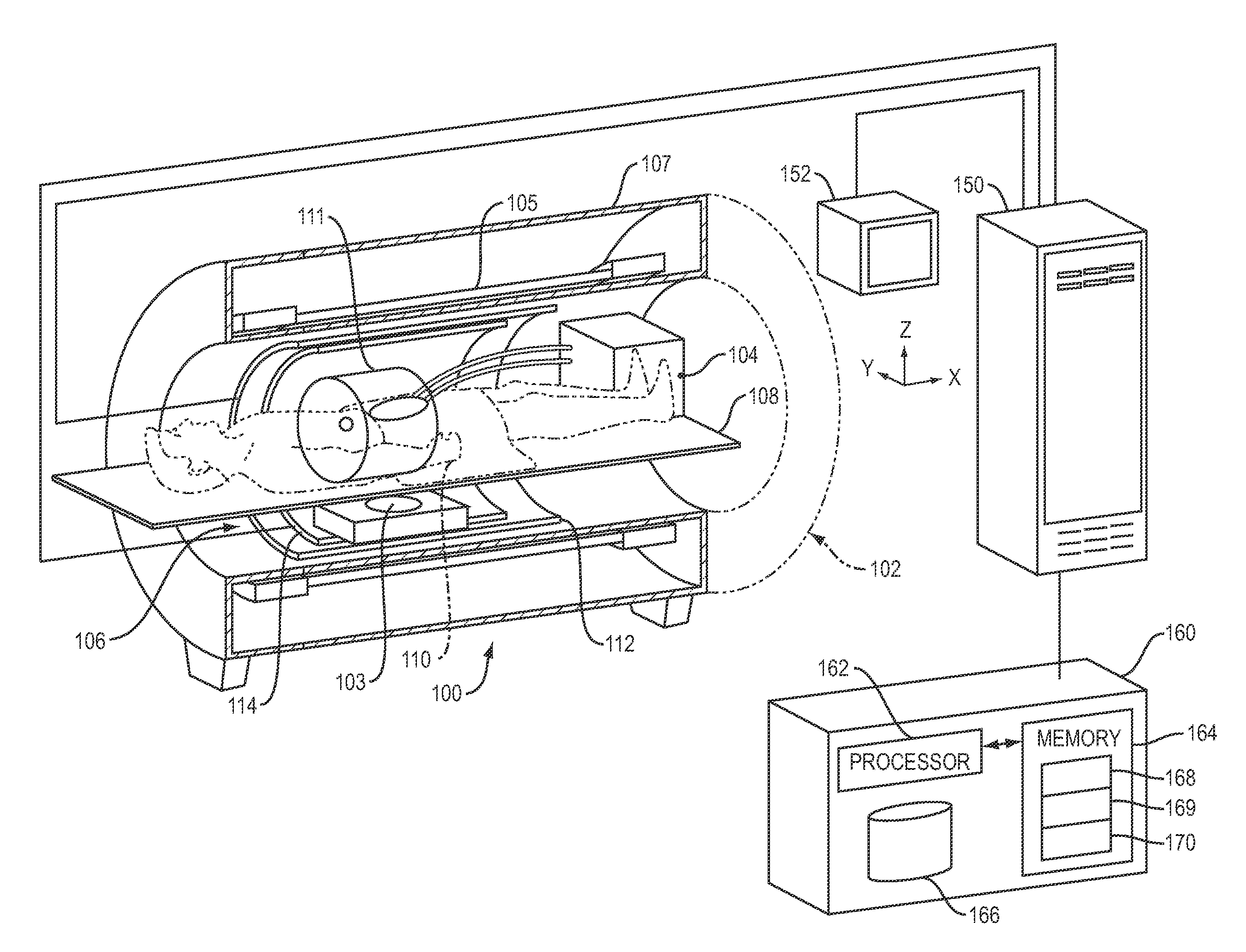
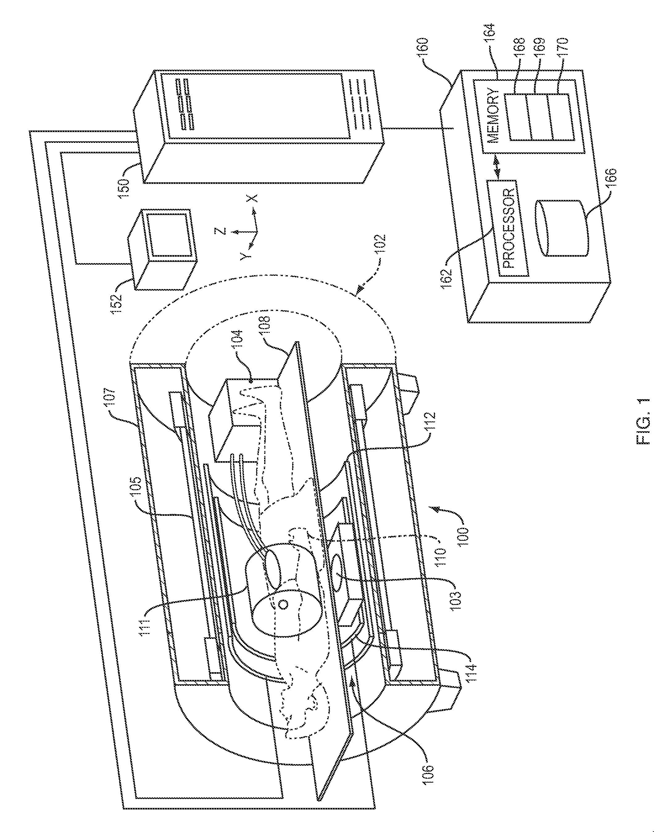
[0024]MRI systems in which the techniques described herein may be implemented are well-known in the art; an exemplary system is shown in FIG. 1. The illustrated system 100 comprises an MRI machine 102 and, when an MR-guided thermal procedure is being performed, a thermal therapy device 103 that may be disposed within the bore of the MRI machine 102. The thermal therapy device 103 may be, for example, an ultrasound transducer, an RF or microwave ablation device, a laser, or any other device adapted to heat a target tissue, and may be configured either for placement outside the patient or for insertion into the patient's body. A controller associated with the thermal treatment device 103 may drive the device in accordance with a treatment protocol and / or based MRI data obtained during the treatment procedure. The system 100 may further include an apparatus 104 for actively cooling healthy tissue near the target tissue to avoid damage due to incidental overheating. The cooling apparatu...


PUM


Abstract

During the thermal treatment of an anatomical zone of interest, tissue temperature within the zone may be determined with a computational model whose parameters are adjusted using spectroscopy-based temperature measurements at interfaces of fat and non-fat tissues.

Description

CROSS-REFERENCE TO RELATED APPLICATION[0001]This application claims priority to and the benefit of U.S. Provisional Application No. 61 / 384,900, filed on Sep. 21, 2010, the entire content of which is hereby incorporated herein by reference.FIELD OF THE INVENTION[0002]The present invention relates to magnetic resonance (MR) thermometry, and, in particular, to the use of MR thermometry for monitoring tissue temperature during thermal treatment of internal tissues.BACKGROUND OF THE INVENTION[0003]MR imaging of internal body tissues may be used for numerous medical procedures, including diagnosis and surgery. In general terms, MR imaging starts by placing a subject in a relatively uniform, static magnetic field. The static magnetic field causes hydrogen nuclei spins to align with and cause a net magnetization in the general direction of the magnetic field. Radio-frequency (RF) magnetic field pulses are then superimposed on the static magnetic field to flip some of the aligned spins, caus...

Claims


Application Information

Patent Timeline
Patent Type & Authority Applications(United States)
IPC IPC(8): A61B5/055
CPCG01R33/4814G01R33/4804
Inventor VORTMAN, KOBIFREUNDLICH, DAVIDVITEK, SHUKI
Owner INSIGHTEC
Why Eureka
Try Eureka