3D Model Creation of Anatomic Structures Using Single-Plane Fluoroscopy

a single-plane fluoroscopy and anatomic structure technology, applied in the field of medical imaging, can solve the problems of analyze the structure of anatomic structures, inability to accurately capture ecg and respiration gating and non-real-time data, and long process of electroanatomic map creation

Active Publication Date: 2012-03-22
APN HEALTH
View PDF6 Cites 87 Cited by
  • Summary
  • Abstract
  • Description
  • Claims
  • Application Information

AI Technical Summary

Benefits of technology

[0011]It is an object of the present invention to provide a medical imaging system which creates 3D models of the heart by identifying the various positions of a catheter within 3D anatomical structures such as cardiac chambers using only a single-plane fluoroscopic system, thus overcoming many of the shortcomings of the prior art imaging systems discussed above.

Problems solved by technology

However, creation of an electroanatomic map may be a lengthy process involving the tagging of many points, depending upon the spatial details needed to analyze a given arrhythmia.
Lack of accurate ECG and respiration gating and non-real-time data are other limitations of this technique.
Furthermore, the catheters used are very expensive and fluoroscopy is always used as a backup to identify the location of catheters.
Again, like the CARTO system, the EnSite system is very expensive, its resolution depends on the number of points taken, and a fluoroscopic system is commonly used to confirm the location of catheters.
One limitation of the LocaLisa system is that it merely provides the user with information about the catheter position—no geometric anatomical model can be created.
As described above, these technologies have several limitations.
Another significant limitation is that the heart is essentially considered a rigid body over which maps such as activation map are displayed.
Also, cardiac chamber distortion due to cardiac and respiratory motion is not taken into account if a significant change in heart rate occurs from the time the map was created to the time therapy is delivered.
However, the biggest drawback, as described before, is that these systems are expensive, require separate mapping systems, and do not provide real-time visualization of the chamber.
However, in the past, fluoroscopy has not been used to create 3D maps since it provides only two-dimensional images.
Furthermore, unlike anatomical systems described before, anatomical maps, electrical maps and voltage maps cannot be created by currently-available fluoroscopy systems.

Method used


Image

  • 3D Model Creation of Anatomic Structures Using Single-Plane Fluoroscopy
  • 3D Model Creation of Anatomic Structures Using Single-Plane Fluoroscopy
  • 3D Model Creation of Anatomic Structures Using Single-Plane Fluoroscopy

Examples


Embodiment Construction

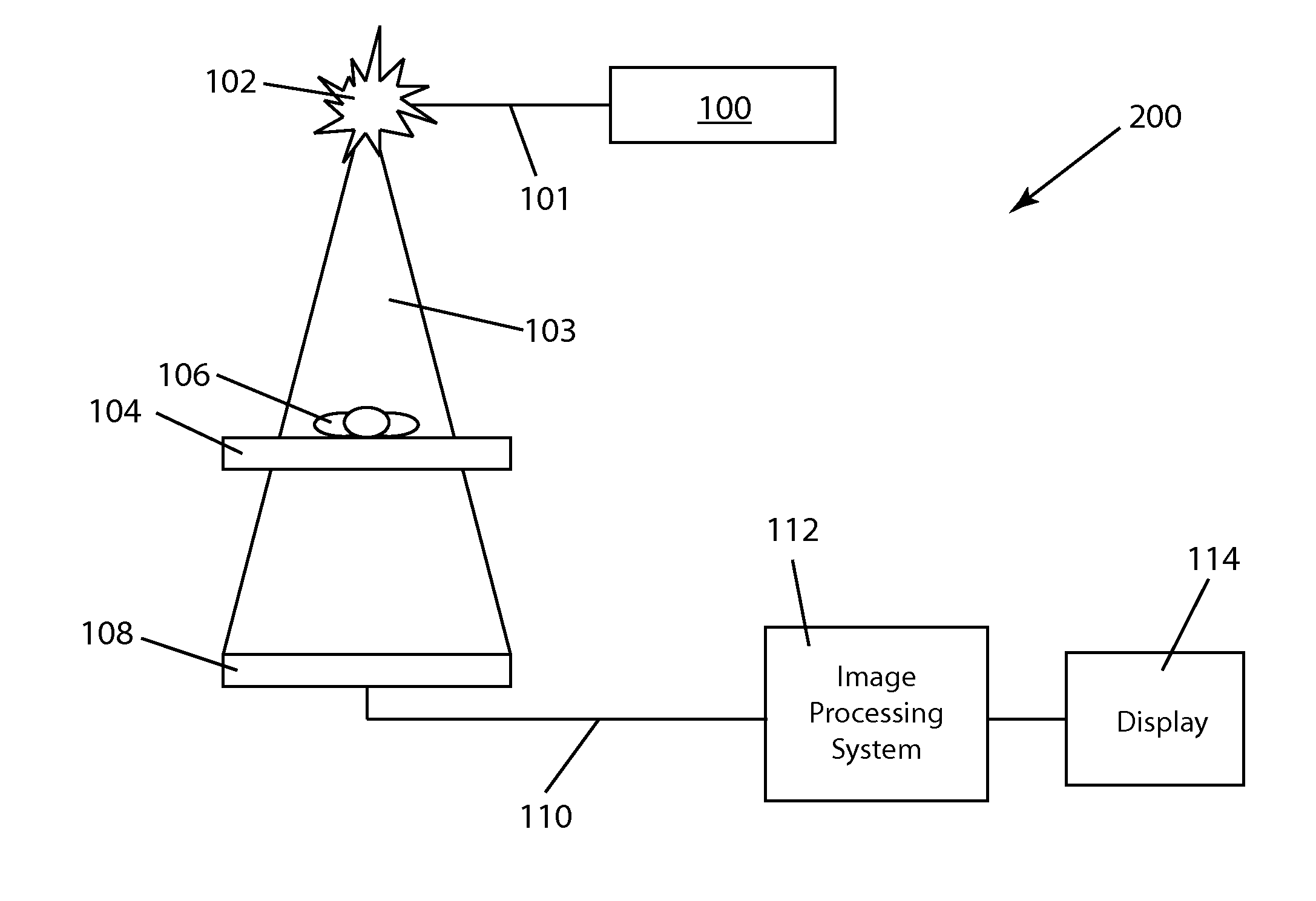
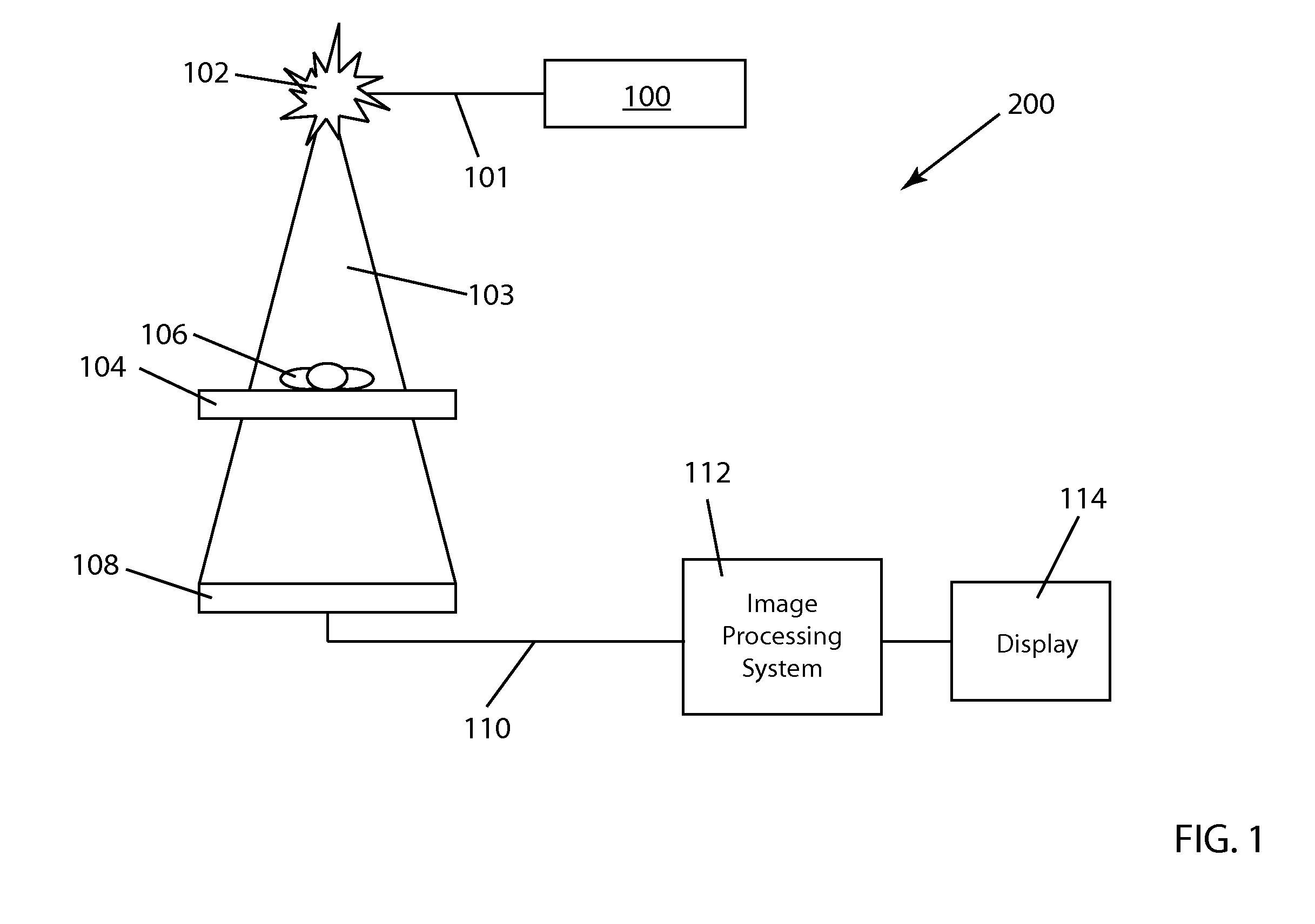
[0034]FIG. 1 illustrates the basic elements of a conventional fluoroscopy image acquisition system 200 used to acquire fluoroscopic image data. The imaging process for conventional fluoroscopy involves an X-ray tube 102 which sends an X-ray beam 103 through a patient 106 on a table 104. X-ray generation is initiated by pushing on a paddle 100 which is connected to the X-ray tube 102 by a communication link 101. A detector 108 includes an image intensifier (within detector 108) which receives the X-rays transmitted through patient 106 and transforms the X-ray energy into light. A video camera (also within detector 108) converts the light into an analog electrical signal which is then sent along communication link 110 to an analog-to-digital converter in an image processing unit 112. Image data operated on within image processing system 112 is then displayed on a computer display 114.

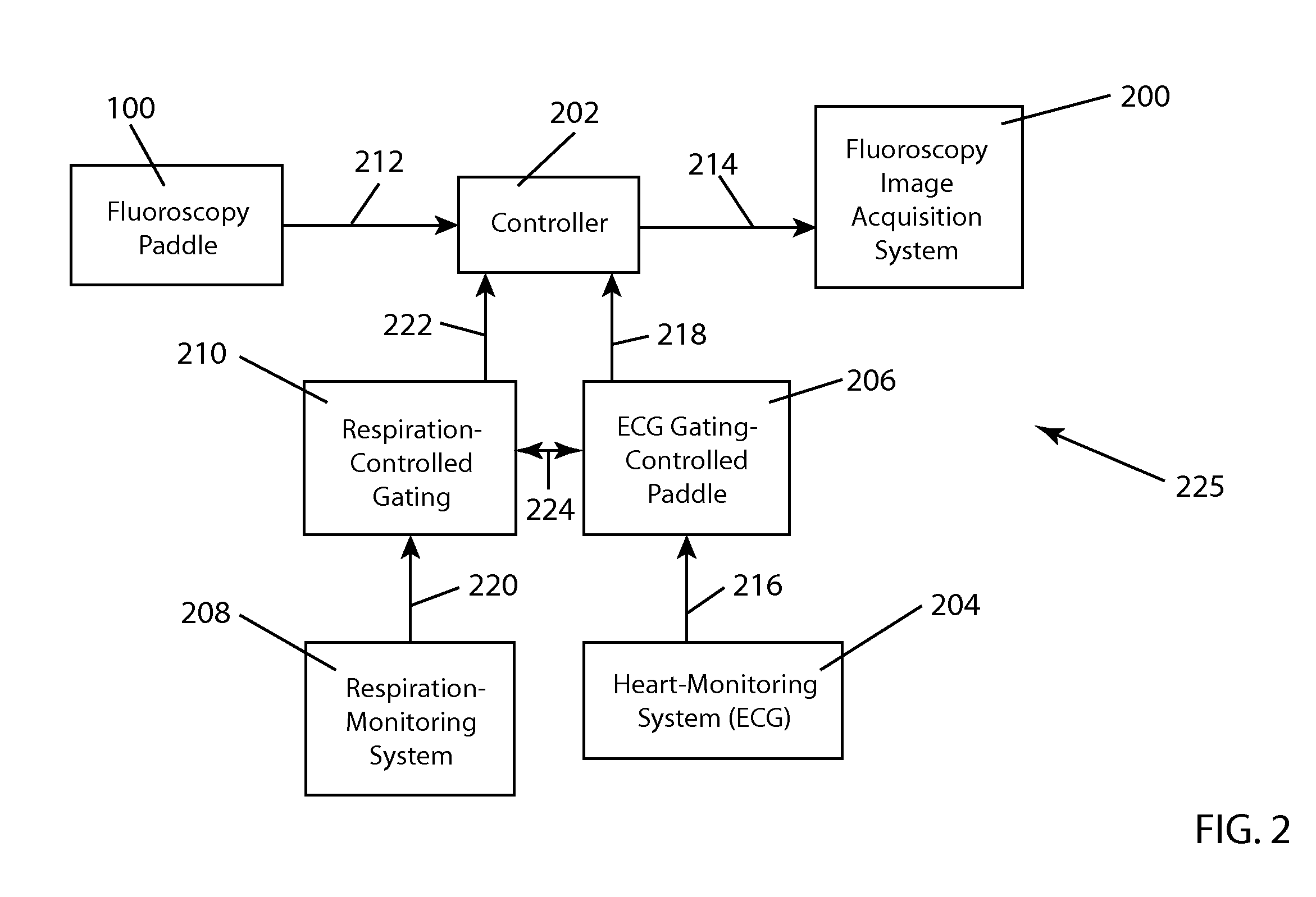
[0035]The process of cardiac and respiratory gating has been described in U.S. patent application Ser....


PUM


Abstract

A method for 3D reconstruction of the positions of a catheter as it is moved within a region of the human body, comprising: (a) ascertaining the 3D position of a point on a catheter for insertion in the body region; (b) acquiring a fixed angle, single-plane fluoroscopic image of the body region and of the catheter; (c) transferring the image data and catheter-point position to a computer; (d) determining the 2D image coordinates of the point on the catheter; (e) changing the length of catheter insertion by a measured amount; (f) thereafter acquiring a further single-plane fluoroscopic image of the body region and the catheter from the same angle, transferring the length change and additional image data to the computer, and determining the 2D image coordinates of the point on the catheter; (g) computing the 3D position of the catheter point; and (h) repeating steps e-g plural times. A 3D model is constructed by assembling the plural 3D positions of the point within the body region into a 3D model of the region.

Description

FIELD OF THE INVENTION[0001]The present invention generally relates to the field of medical imaging and more particularly to three-dimensional image creation using imaging only from 2D fluoroscopy.BACKGROUND OF THE INVENTION[0002]Anatomical mapping systems provide the three-dimensional (3D) position of a navigational catheter within the cardiac chamber of interest and, in some instances, can also be used to construct 3D maps of the cardiac chamber. Systems such as CARTO (Biosense Webster, Diamond Bar, Calif.) use the electromagnetic position of the catheter tip relative to an electromagnetic locator pad which is placed below the patient and a reference catheter at a fixed external (usually posterior) location. LocaLisa (Medtronic, Minneapolis) and NavX (St. Jude's Medical, Minneapolis, Minn.) systems use voltage gradients generated by external electrical fields to spatially orient and localize the catheter tip. The EnSite system (St. Jude's Medical) uses an electrically-coded cathet...

Claims


Application Information

Patent Timeline
Patent Type & Authority Applications(United States)
IPC IPC(8): A61B5/05
CPCA61B6/12A61B6/466A61B6/541A61B6/503A61B6/487
Inventor SRA, JASBIRMERRILL, STEPHEN J.
Owner APN HEALTH
Why Eureka
Try Eureka