Rubber-steel cord composite and tire using the same

a technology of rubber-steel cord and composite material, which is applied in the direction of heavy-duty tyres, transportation and packaging, cycles, etc., can solve the problems of insufficient strength and inability to improve above two types of properties at the same time, and insufficient rigidity of rubber itself. , to achieve the effect of low rigidity, high rigidity, and flexible properties

Inactive Publication Date: 2012-03-29
BRIDGESTONE CORP
View PDF2 Cites 0 Cited by
  • Summary
  • Abstract
  • Description
  • Claims
  • Application Information

AI Technical Summary

Benefits of technology

[0046]According to the present invention, by the structure described above, a rubber-steel cord composite can be realized in which low rigidity and flexible properties can be obtained in a low-strain region, and in which on the other hand, in a high-strain region, high rigidity can be obtained.
[0023]In addition, another object of the present invention is to provide a motorcycle pneumatic radial tire having improved turning steering performance (cornering performance) without degrading various performances, such as straight running performance, high-speed performance, comfort, and uniformity, the motorcycle pneumatic radial tire including a spiral belt layer which is realized by using a cord having a structure in which rubber is not enclosed inside as a belt reinforcing member so that low rigidity and flexible properties are obtained in a low-strain region and on the other hand, high rigidity is obtained in a high-strain region.
[0048]Furthermore, according to the present invention, since a reinforcing cord having the predetermined structure described above is applied to the outermost layer of the belt of a large pneumatic radial tire, a large pneumatic radial tire having improved durability can be realized by improving the anti-cutting performance against external scratches. In addition, the steel cord used in the present invention has superior productivity; hence, compared to a steel cord having a multi-twisted structure which has been generally used, a merit of low price can also be obtained.

Problems solved by technology

When a rubber-steel cord composite in which rubber is reinforced by at least one steel cord is applied to a rubber product, insufficient strength and rigidity of rubber itself can be increased; hence, the rubber-steel cord composite has been widely used for various rubber products, such as a tire, a belt, and a hose.
For example, for a product such as a tire, in order to improve contact conditions with a road surface at the initial stage, the flexibility is required; however, on the other hand, when an input force is further applied during cornering or the like, high rigidity is required.
However, even when the ratio of the steel cord used as a reinforcing member is changed, the above two types of properties cannot be simultaneously improved.
In addition, when a so-called spiral belt layer is applied to a motorcycle pneumatic radial tire, the spiral belt layer being formed by spirally winding a belt member including one cord or at least two parallel cords embedded in coating rubber in a tire rotation axis direction at an angle toward approximately a tire circumferential direction, the high-speed durability, straight running stability, uniformity performance, acceleration performance, and the like can be improved; however, on the other hand, reaction becomes slow when the direction of a vehicle is changed, so that the nimble performance is degraded.
Through investigation on the mechanism in which the above two types of properties cannot be simultaneously obtained, it was found that although the rigidity can be increased by providing a spiral belt layer, the degree of contact conditions with a road surface is degraded thereby, and the ground contact response of a tire becomes inferior, so that the nimble performance is lost.
Furthermore, a general dump truck tire that may run on a waste land in some cases is forced to run on a road surface on which crushed rocks are spread.
Accordingly, a belt-cut failure is liable to occur, and a tire failure may be directly caused thereby, or a steel cord may be corroded by water permeated from a cut position to cause a separation failure; hence, one of the above failures occurs, and the tire life is disadvantageously decreased.

Method used


Image

  • Rubber-steel cord composite and tire using the same
  • Rubber-steel cord composite and tire using the same
  • Rubber-steel cord composite and tire using the same

Examples


example 1

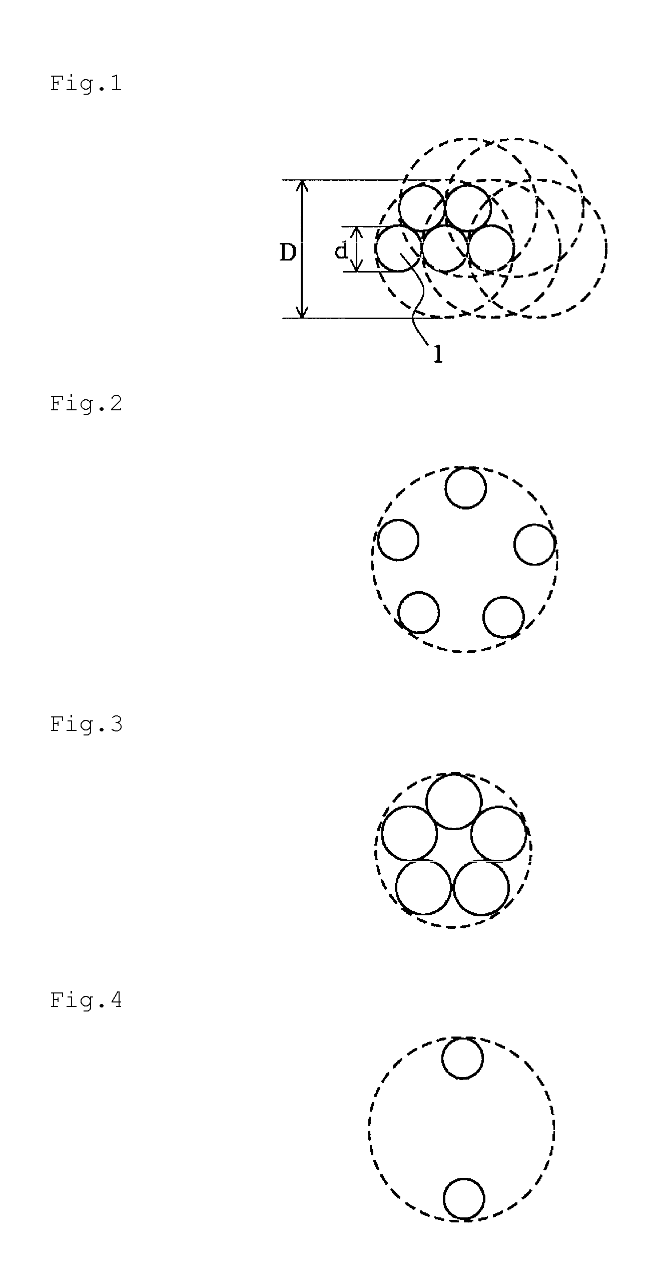
[0098]By using steel linear objects (filaments or strands (brass plating): 63 percent by weight of Cu and 37 percent by weight of Zn) subjected to shape forming, which had shape forming amounts and pitches shown in the following Table 1, rubber-steel cord composites were formed in accordance with the conditions shown in the following Table 1. As coating rubber, a rubber composition was used including 100 parts by weight of natural rubber (NR), 55 parts by weight of carbon black (HAF), 7 parts by weight of zinc oxide (ZnO), 5 parts by weight of sulfur, and 0.1 parts by weight of a Co salt (cobalt naphthenate).

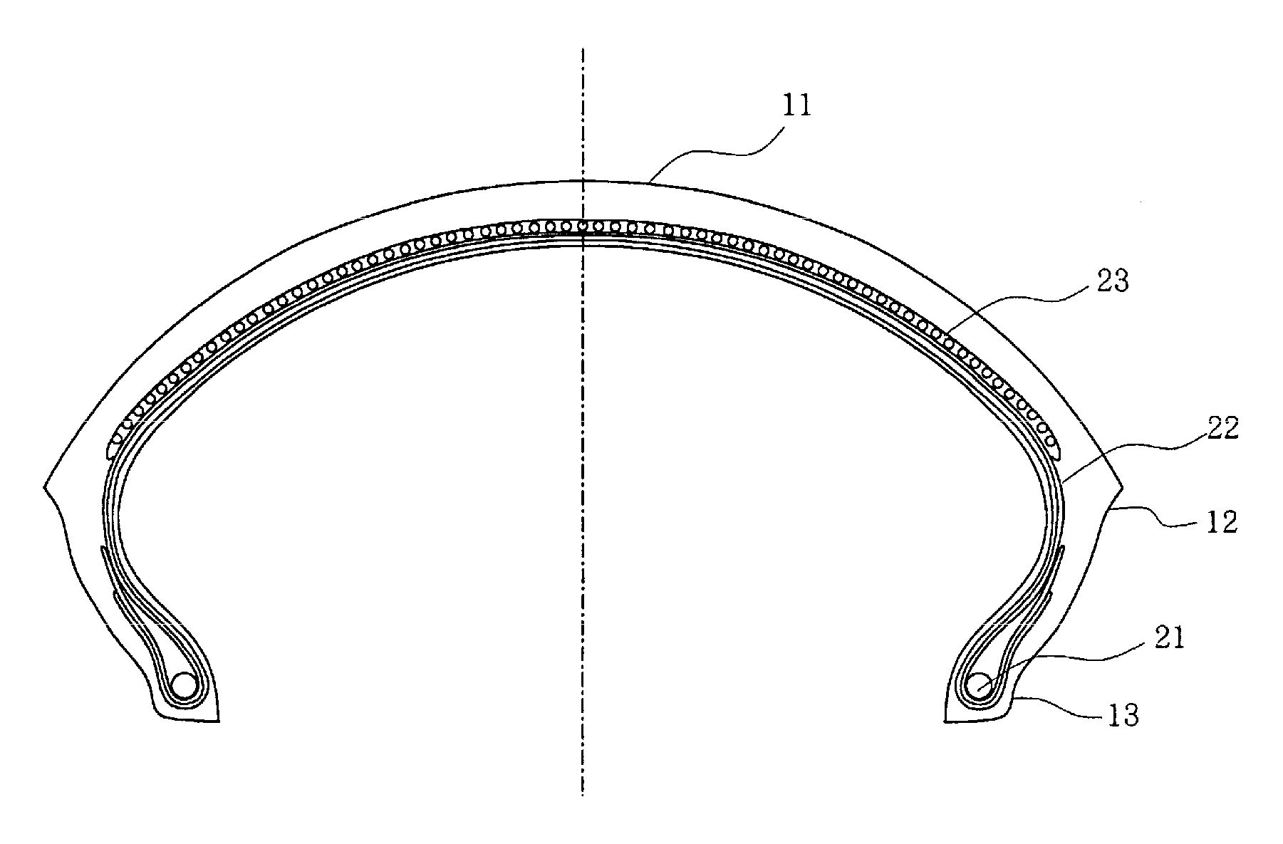
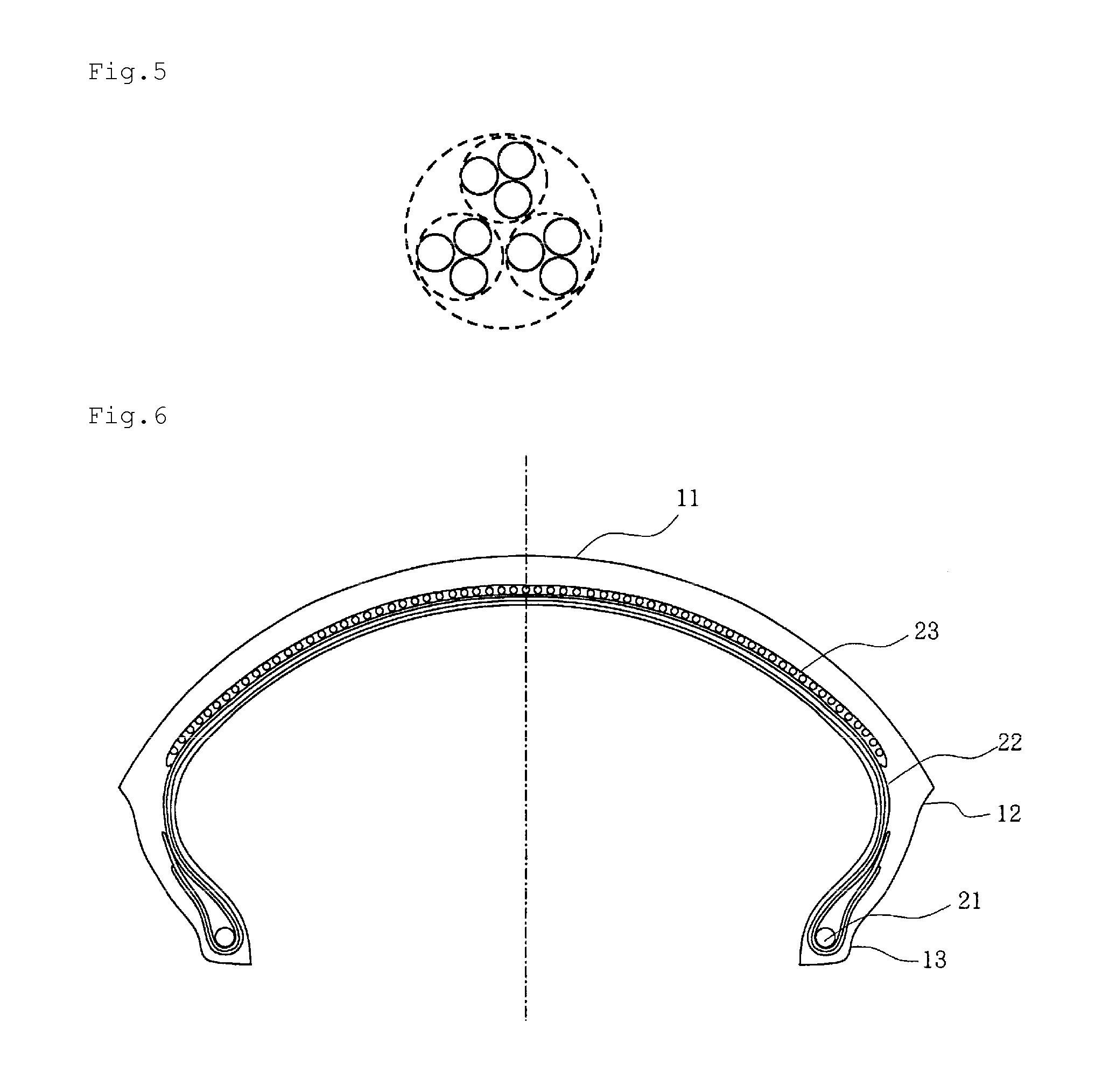
[0099]The rubber-steel cord composites thus formed were each applied at an embedded number of 40 per 50 mm to a spiral belt layer of a motorcycle pneumatic radial tire (MC tire) (tire size: 190 / 50ZR17) having the spiral belt structure shown in FIG. 6, and the vibration absorption performance and the cornering performance were evaluated as described below. The results are also sh...

example 2

[0103]By using steel linear objects (filaments or strands (brass plating): 63 percent by weight of Cu and 37 percent by weight of Zn) subjected to shape forming, which had shape forming amounts and pitches shown in the following Table 2, rubber-steel cord composites were formed in accordance with the conditions shown in the following Table 2. As coating rubber, a rubber composition similar to that used in Example 1 was used.

[0104]The rubber-steel cord composites thus formed were each applied at an embedded number of 40 per 50 mm to a spiral belt layer of a motorcycle pneumatic radial tire (MC tire) (tire size: 190 / 50ZR17) having the spiral belt structure shown in FIG. 6, and the vibration absorption performance and the cornering performance were evaluated in a manner similar to that in Example 1. The results are also shown in the following Table 2.

TABLE 2ComparativeComparativeComparativeComparativeExample 2-1Example 2-2Example 2-3Example 2-4Example 2-1Cord StructureOpen*1CloseOpenMu...

example 3

[0106]By using steel filaments (brass plating): 63 percent by weight of Cu and 37 percent by weight of Zn), rubber-steel cord composites of examples and comparative examples were formed in accordance with the conditions shown in the following Table 3. As coating rubber, a rubber composition similar to that used in Example 1 was used. In addition, the cord of each example was a non-twisted cord in which a plurality of steel filaments subjected to spiral shape forming at substantially identical pitches was bundled in an approximately identical phase without being twisted.

[0107]The rubber-steel cord composites thus obtained were each applied to the outermost layer 43d of the four layers of belts of a truck / bus pneumatic radial tire of a tire size 11R22.5 having the tire structure shown in FIG. 7, so that individual test tires were formed. After the test tires thus formed were made to run 100,000 km on a road surface having a bad road rate of 20% at an inside pressure of 830 kPa and a l...


PUM

PropertyMeasurementUnit
elongationaaaaaaaaaa
center angleaaaaaaaaaa
breaking elongationaaaaaaaaaa

Abstract

A rubber-steel cord composite is provided having nonlinear physical properties even in a rubber characterized by incompressive properties after vulcanization, and hence the rubber-steel cord composite can show low rigidity and flexible properties in a low-strain region and, on the other hand, can show high rigidity in a high-strain region. The rubber-steel cord composite is provided by bundling steel linear objects 1 subjected to spiral shape forming at substantially identical pitches in an approximately identical phase without twisting, the steel cord being embedded in rubber.

Description

CROSS REFERENCE TO RELATED APPLICATIONS[0001]This application is a divisional of pending U.S. application Ser. No. 12 / 161,346, filed Sep. 30, 2008, which is a National Stage of International Application No. PCT / JP2007 / 508291 filed Jan. 19, 2007, claiming priority based on Japanese Patent Application No. 2006-012605, filed Jan. 20, 2006, Japanese Patent Application No. 2006-012624, filed Jan. 20, 2006, Japanese Patent Application No. 2006-127401, filed May 1, 2006, and Japanese Patent Application No. 2006-129916, filed May 9, 2006, the contents of all of which are incorporated herein by reference in their entirety.TECHNICAL FIELD[0002]The present invention relates to a rubber-steel cord composite, and more particularly relates to a rubber-steel cord composite suitably applied to various rubber products, such as a tire, for reinforcement.[0003]In addition, the present invention relates to a motorcycle pneumatic radial tire (hereinafter referred to as a “motorcycle tire” in some cases)...

Claims


Application Information

Patent Timeline
Patent Type & Authority Applications(United States)
IPC IPC(8): B60C9/18
CPCB60C9/0007Y10T152/10765D07B1/0613D07B1/062D07B1/0646D07B1/16D07B2201/1092D07B2201/2007D07B2201/2011D07B2201/2021D07B2201/2022D07B2201/2033D07B2201/2044D07B2205/3089D07B2401/2005D07B2501/2046B60C9/2006Y10T152/1081B60C2200/10B60C2200/06B60C9/005D07B2801/18
Inventor ISHIZAKA, HIROKIIKEHARA, KIYOSHI
Owner BRIDGESTONE CORP
Why Eureka
Try Eureka