Over-temperature protection circuit for power devices

a protection circuit and power device technology, applied in the direction of dynamo-electric converter control, dc motor speed/torque control, electric/dynamo-electric converter starters, etc., can solve the problems rapid heating time lag phenomenon, etc., to effectively reduce the risk of overheating failure of the power device, increase extra hardware cost, and quickly shut down the power device

Active Publication Date: 2012-03-29
CHERVON HK LTD WANCHAI
View PDF19 Cites 11 Cited by
  • Summary
  • Abstract
  • Description
  • Claims
  • Application Information

AI Technical Summary

Benefits of technology

[0011]In order to overcome the disadvantages and drawbacks in the prior art, the present disclosure proposes, among other things, an over-temperature protection circuit for the power devices in DC electric tools to mitigate the effect of the above problems, and also proposes an electric tool using such circuit.
[0013]In at least one embodiment, the over-temperature protection circuit of the DC electric tool is combined with MCU software control to predict whether the overheating phenomenon will appear during the operation of the power device, so as to shut down the power device quickly and effectively lower the risk of the overheating failure of the power device.
[0014]In addition, in one example, the present disclosure uses only existing current sampling circuits, without increasing extra hardware cost.
[0015]Meanwhile, the over-temperature protection circuit of the DC electric tool according to an example of the present disclosure is combined with the conventional measures like as the over-temperature protection by means of measuring the outside temperature and the over current protection etc, so as to protect the power device more effectively and improve the lifetime of the tool.

Problems solved by technology

Speed control by a larger current will certainly result in rapid heating of the power device, and furthermore the fast rising operating temperature will result in rapid overheating failure of the power device.
Because heat transferring between objects is a slow procedure, this factor results in that the temperature sampled from practical applications always lags behind the actual operating temperature of the power device.
1) The significant heater of a power device is typically the inner core thereof, and therefore a time lag phenomenon exists during heat transferring from the inner core to the periphery of the power device.
2) Typically, only when the temperature of the whole body of a temperature measurement element reaches the temperature to be measured, can its featured resistance be truly consistent with the temperature to be measured. But a time lag phenomenon exists before the temperature of the whole body of the temperature measurement element reaches to a certain temperature.
3) If a packaged temperature measurement element is mounted on the packaged body or heatsink of a power device, there is a time lag phenomenon of the temperature measurement because the thermal conductivity of the package material of the power device or the temperature measurement element is lower.
4) If the package shape of a temperature measurement element does not closely correspond to the shape of a power device, there exists an air gap therebetween after installation, and because the thermal conductivity of air is lower, a significant time lag phenomenon of the temperature measurement exists. It is oftentimes necessary to fill the thermally conductive material in the gap to improve the thermal conductivity between the temperature measurement element and the power device, but a time lag phenomenon still exists. Moreover, the operation for filling the thermally conductive material into the gap has some uncertainties such that the thermal conductivities of the temperature measurement element and the power device are not consistent with each other in mass production, thus increasing the difficulty of the temperature compensation.
5) According to the internal structure of a power device, the temperature of its heatsink is closer to that of the inner core. When a temperature measurement element is mounted to the heatsink of the power device, as the heatsink of the power device usually has an electric network, the temperature measurement element has to be electrically isolated from the heatsink of the power device, which lowers the thermal conductivity between the temperature measurement element and the power device. As a result, the measured temperature lags the actual temperature of the power device.
Due to the above observed phenomena, the external temperature measurement element can not accurately track the core temperature change of the power device in real time and the real-time monitoring is insufficient for some situations, which may result in the inability to shut down the power device in time and may result in the overheating failure of the power device.

Method used


Image

  • Over-temperature protection circuit for power devices
  • Over-temperature protection circuit for power devices
  • Over-temperature protection circuit for power devices

Examples


Embodiment Construction

[0020]The present disclosure will be described in detail by various examples in conjunction with the accompanying drawings as follows.

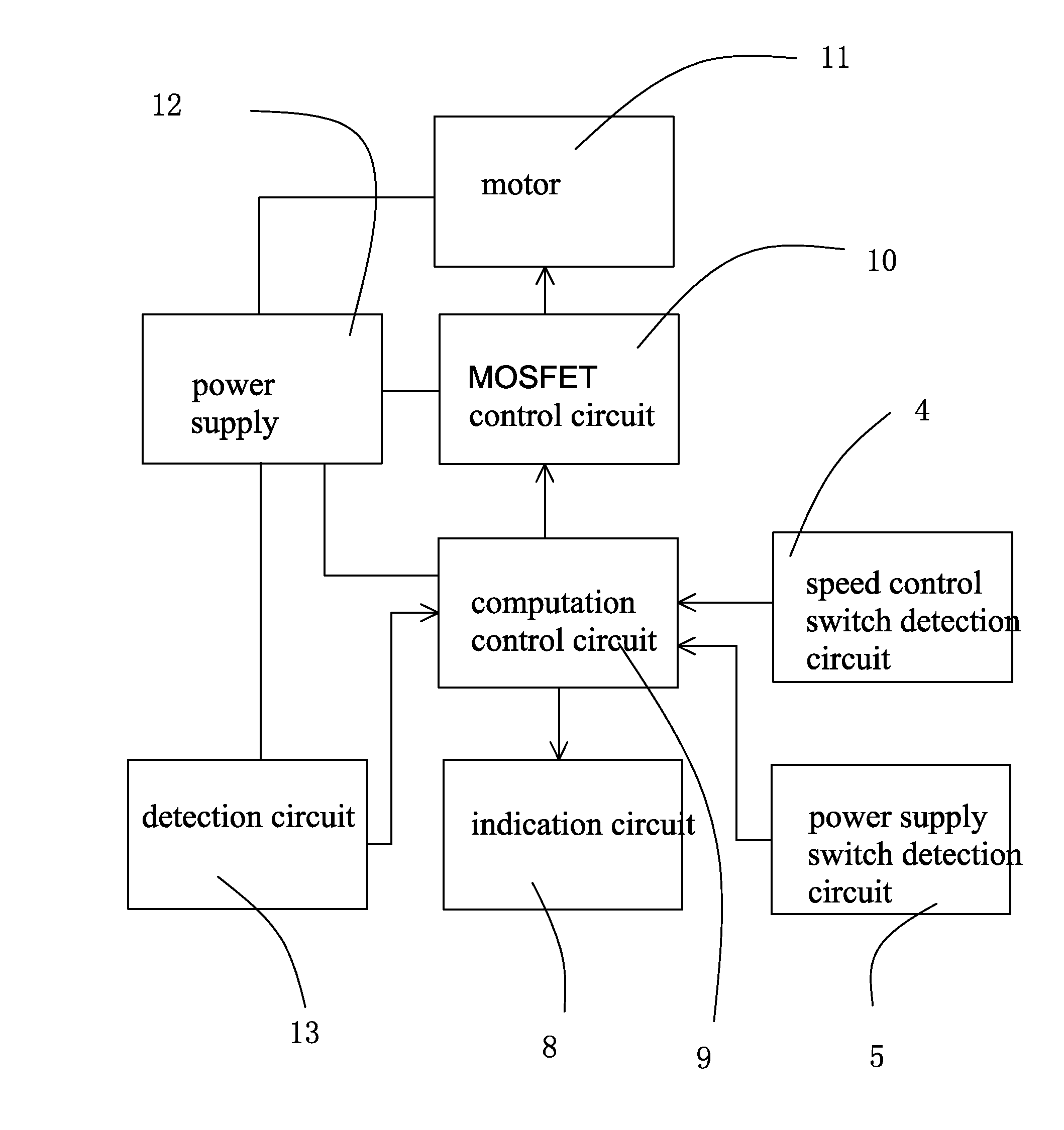
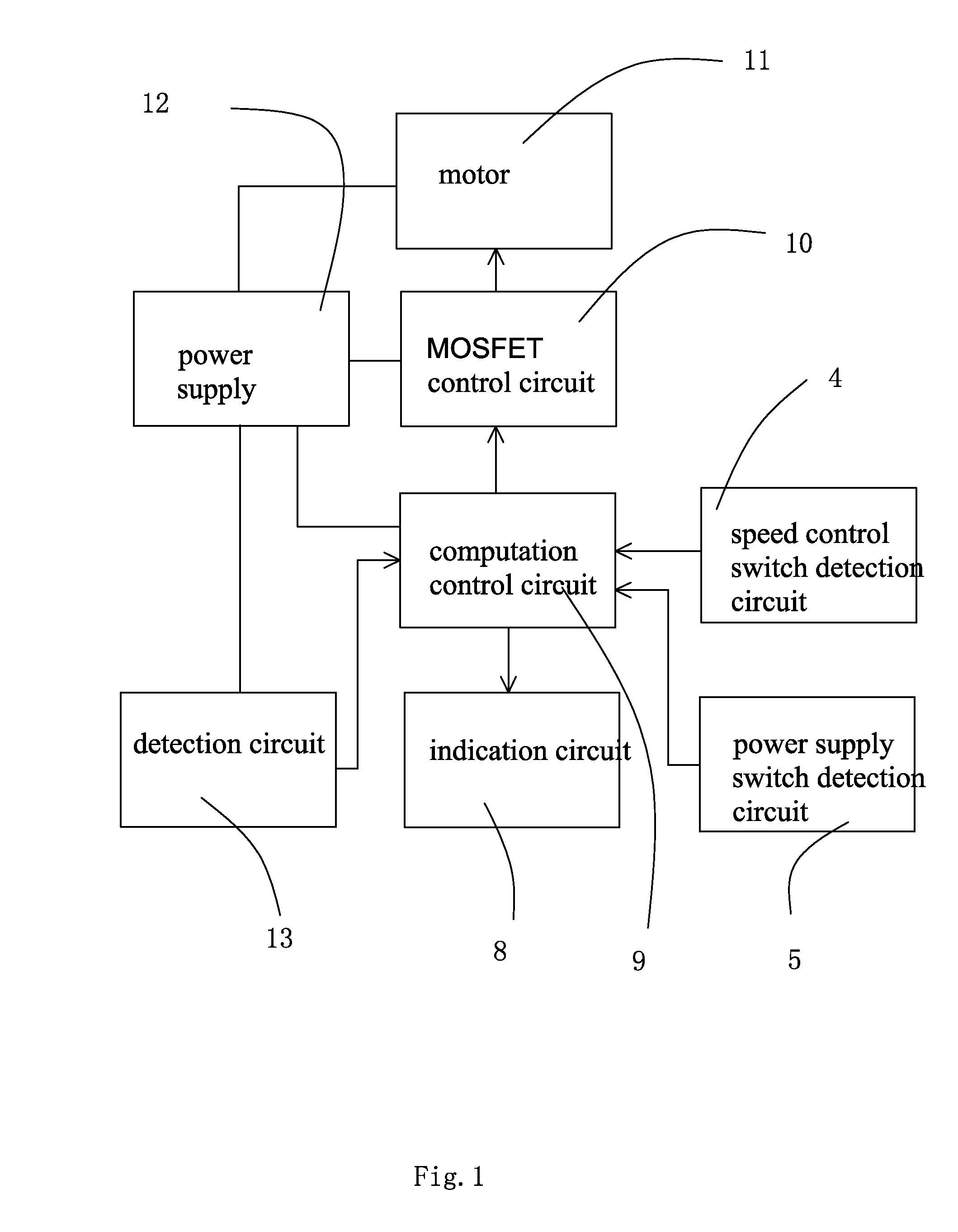
[0021]Under normal operating conditions, a direct current (DC) electric tool comprises a motor installed in a housing, a switch, and a battery pack comprising multiple rechargeable batteries for providing power for the electric tool.

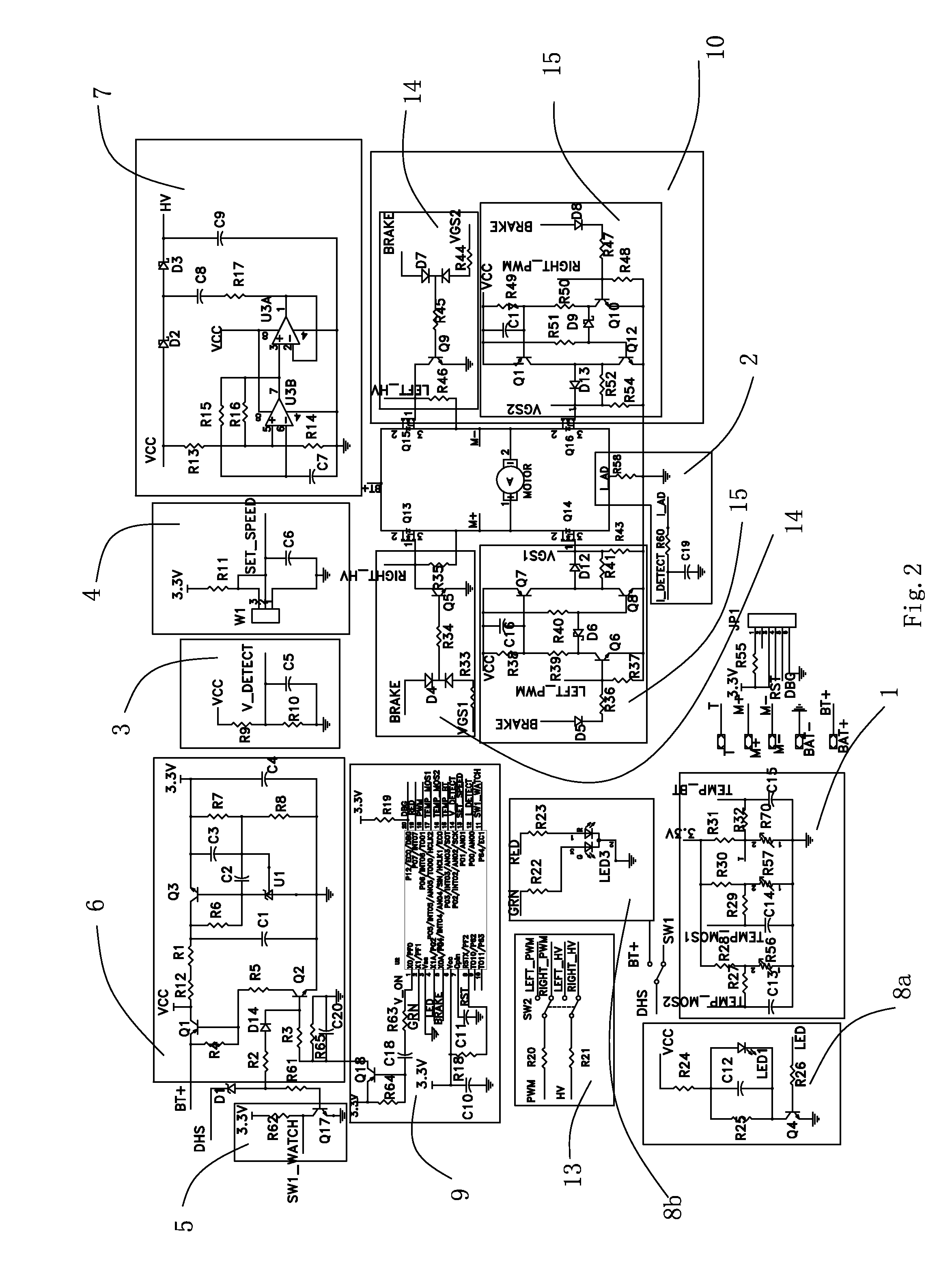
[0022]The DC electric tool has speed control function, which is realized by different average currents obtained in the coils of the DC electric motor by modulating the PWM duty cycle represented by on and off of the power device. The power device can be IGBT, MOSFET, and SCR etc. In the present disclosure, MOSFET is described.

[0023]The heating power of a MOSFET is also the power loss thereof, mainly comprising the conductive loss and the switching loss, while the switching loss comprises the turn-on loss and the turn-off loss, wherein:

The conductive loss: P(conduct)=Ipk2×RDS(on)×D  equation 1

Wherein

[0024]D=TONTequation2

[00...


PUM


Abstract

An over-temperature protection circuit for a direct current (DC) electric tool includes a current detecting circuit electrically coupled to a battery pack, a power device control circuit electrically coupled to an electric motor of the DC electric tool and a power device for controlling the power state of the circuit. A computation control circuit controls the power supply of the motor according to the circuit current value detected by the current detecting circuit. When the electric motor is not in a speed control state, the allowable current passing through the over-temperature protection circuit of the DC electric tool cannot exceed a preset first current value. When the electric motor is in the speed control state, the allowable current passing through the over-temperature protection circuit of the DC electric tool cannot exceed a preset second current value less than the first current value.

Description

CROSS REFERENCE TO RELATED APPLICATION[0001]This application claims the benefit of CN 201010292359.2, filed on Sep. 26, 2010, the disclosure of which is incorporated herein by reference in its entirety.FIELD OF THE DISCLOSURE[0002]The present disclosure relates to an over-temperature protection circuit for direct current (DC) electric tools, and more particularly to an over-temperature protection circuit for power devices in DC electric tools.BACKGROUND OF RELATED ART[0003]Generally, most DC electric tools have speed control functions, and their operating currents are relatively larger. Control devices for DC electric tools are usually power devices like insulated gate bipolar transistor (IGBT), metal-oxide-semiconductor field-effect transistor (MOSFET), etc. Speed control by a larger current will certainly result in rapid heating of the power device, and furthermore the fast rising operating temperature will result in rapid overheating failure of the power device. Currently in orde...

Claims


Application Information

Patent Timeline
Patent Type & Authority Applications(United States)
IPC IPC(8): H02P7/285
CPCH02P29/022H02P29/0055H02P29/032H02P29/64
Inventor SHI, PINGBOYANG, DEZHONG
Owner CHERVON HK LTD WANCHAI
Why Eureka
Try Eureka