
Occluder

a technology of occluder and occluder plate, which is applied in the field of occluder, can solve the problems of insufficient adaptability of occluders known in the prior art to these circumstances, different available space, and high confined space, and achieve the effect of not disturbing the function of the heart valve, small dimensions, and high pressur

Active Publication Date: 2012-03-29
CARAG AG
View PDF5 Cites 30 Cited by
  • Summary
  • Abstract
  • Description
  • Claims
  • Application Information

AI Technical Summary

Benefits of technology

[0015]This occluder has the advantage that it has relatively small dimensions both in the compact, elongate state and also in the expanded state and yet can withstand the high pressure in the area of the ventricular septum. A further advantage is that the occluder in the expanded position of use bears relatively flat on both sides of the ventricular septum, does not protrude or only slightly protrudes into the ventricle, and does not disturb the function of the heart valve. It is also advantageous that the occluder can be opened and expanded in a guided manner and can thus be positioned optimally in the passage.
[0016]In the compact state, the occluder according to the invention is relatively short compared to the known occluders. Typical lengths are 20 mm to 50 mm, preferably 30 mm. In this way, upon introduction into the ventricular septum, the occluder can be better guided round tight curves.
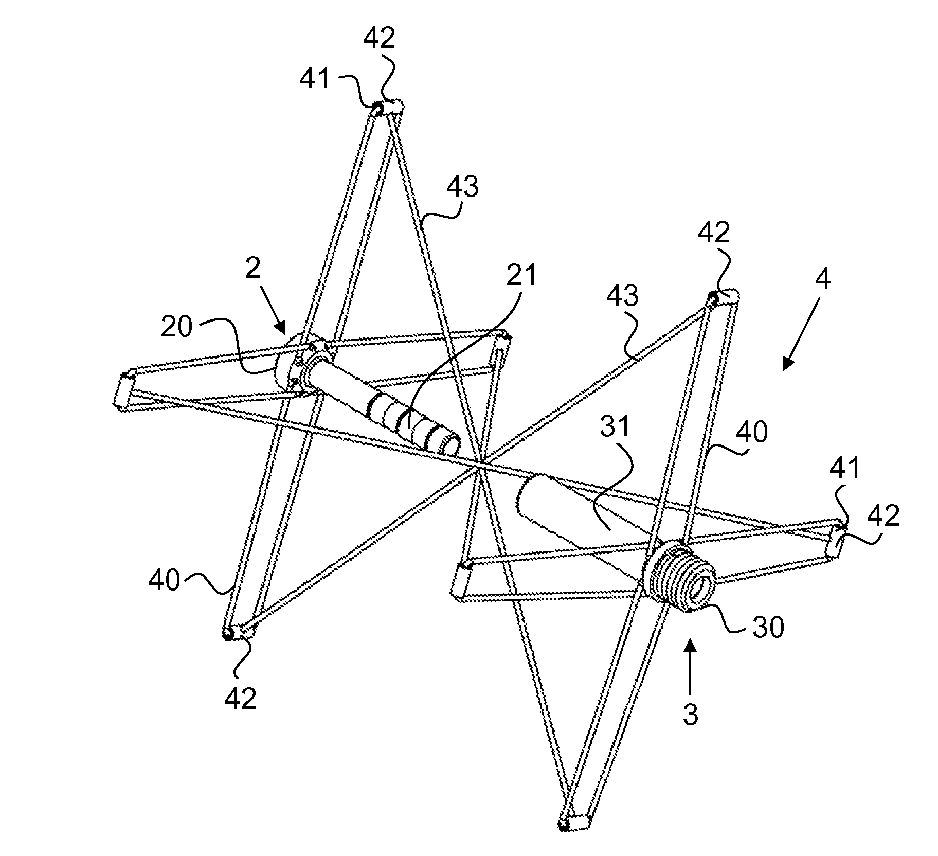
[0019]In a preferred embodiment, each of the fixation arms is bow-shaped or U-shaped with two branches and a bridge joining these branches. The two branches have free ends, which are held pivotably in the proximal or distal axial part. The bridge forms the free end of the fixation arm. This U-shaped design gives stability to the fixation arms, and they can be easily assembled and easily connected to the connecting members.
[0028]The closure body, in particular the tampon, is preferably arranged in an area that is defined on one side by the distal fixation arms and on an opposite side by the proximal fixation arms. In this way, the closure body is located in the passage itself and not on an outer face of the passage. This arrangement of the closure body can also be used in occluders other than those described here and is claimed here as an independent invention. An occluder with at least one closure body arranged in this way permits rapid and optimal closure, even under high pressures. It is advantageous that it does not protrude or only slightly protrudes into the ventricle.

Problems solved by technology

Moreover, the available space is different and also very much more confined than in the atrium.
The occluders known in the prior art are often not optimally adapted to these circumstances.

Method used


Image

  • Occluder
  • Occluder
  • Occluder

Examples


Embodiment Construction

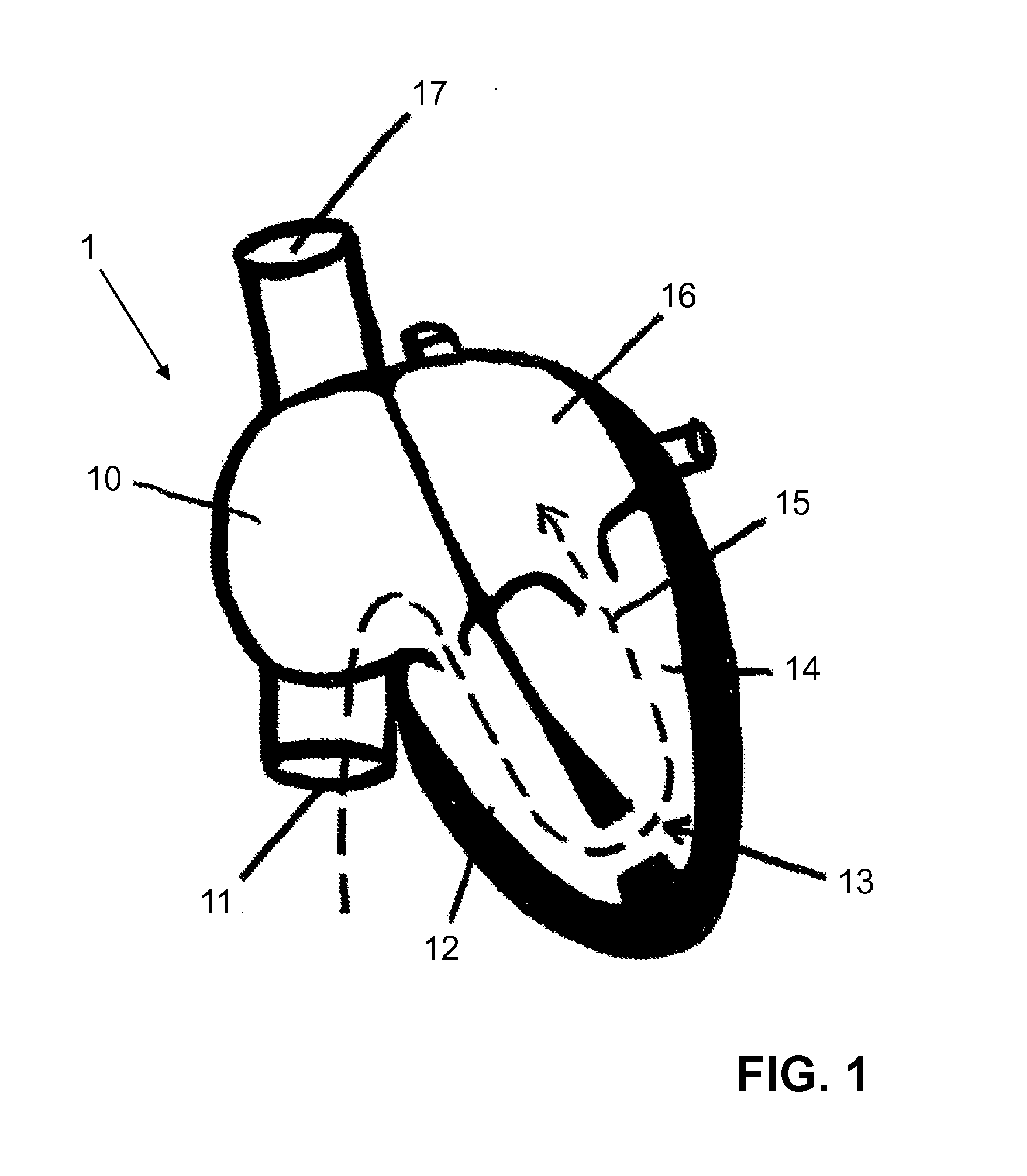
[0046]FIG. 1 shows a view of a human heart 1 with a ventricular septal defect (VSD). The right atrium is designated by reference number 10, the inferior vena cava by 11, the right ventricle by 12, the ventricular septal defect by 13, the left ventricle by 14, the left atrium by 16, and the superior vena cava by 17. The broken arrow 15 indicates the path by which a guide wire is inserted. In this way, an occluder can be brought to the site of the defect by means of a catheter system and can close the defect.

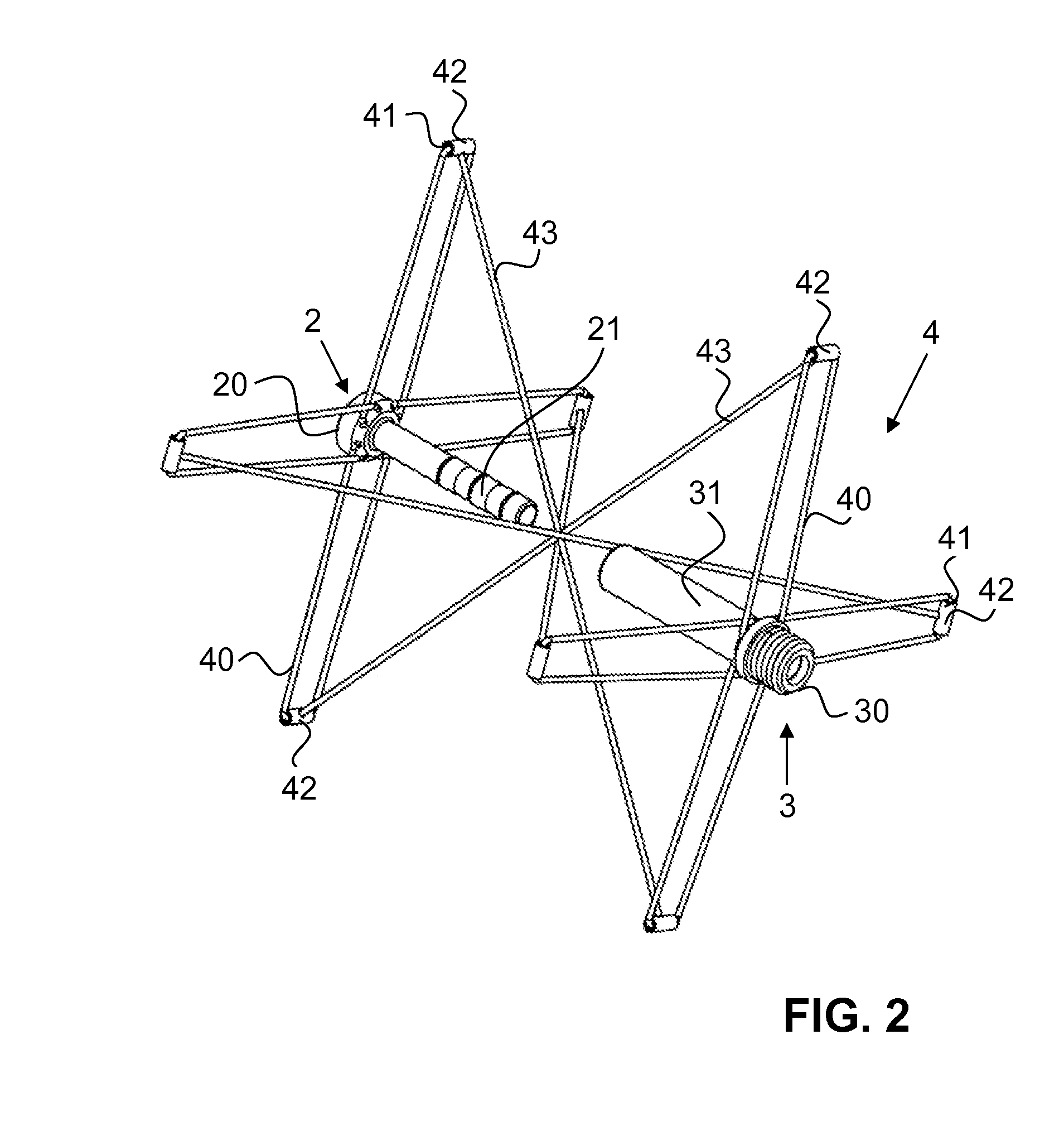
[0047]FIGS. 2 to 6 show a first illustrative embodiment of the occluder according to the invention. In FIG. 2, the occluder is shown in a position between a compact state and an expanded state. It also has a virtual longitudinal axis, which is not shown here. A distal axial part 2 and a proximal axial part 3 are arranged along this longitudinal axis. In the examples described here, the two axial parts serve as coupling parts, which can be inserted one inside the other and thus fix...


PUM


Abstract

The invention relates to an occluder for closing a passage in a circulatory system comprising an expandable fixation unit for fixing the occluder on the passage, wherein the occluder can be transferred in the passage from a compact appearance into an expanded appearance. The occluder has a distal and a proximal axial part, in which the fixation unit is pivotally held. According to the invention, the fixation unit comprises distal fixation arms and proximal fixation arms, wherein the distal fixation arms are pivotally held in the distal axial part and the proximal fixation arms are pivotally held in the proximal axial part. The distal and the proximal fixation arms have free ends, which are interconnected by means of connecting members that can be moved relative to the fixation arms, wherein in each case a distal fixation arm is connected to a proximal fixation arm located diagonally opposed thereto. Said occluder is suited in particular for closing a ventricular septal defect (VSD).

Description

CROSS REFERENCE TO RELATED APPLICATIONS[0001]The present application is a U.S. National Phase Application pursuant to 35 U.S.C. §371 of International Application No. PCT / CH2010 / 000147 filed Jun. 3, 2010, which claims priority to Swiss Patent Application No. 899 / 09 filed on Jun. 10, 2009. The entire disclosure contents of these applications are herewith incorporated by reference into the present application.TECHNICAL FIELD[0002]The present invention relates to an occluder.PRIOR ART[0003]Occluders are implants that are used to close passages in circulatory systems, for example blood vessels or shunt connections, and that are usually positioned and expanded via a sheath introduced into a vein. Occluders are used, for example, to close a persistent ductus arteriosus (PDA), an atrial septal defect (ASD) or a ventricular septal defect (VSD). Other uses in the human or animal body are possible. The form of the occluders is adapted in each case to the corresponding use.[0004]Occluders are k...

Claims


Application Information

Patent Timeline
Patent Type & Authority Applications(United States)
IPC IPC(8): A61B17/03
CPCA61B17/0057A61B2017/00575A61B2017/00588A61B2017/00619A61B2017/00597A61B2017/00601A61B2017/00606A61B2017/00592
Inventor STEINER, CLAUDIOHUMMEN, JORGWEISHAUPT, ANDREAS
Owner CARAG AG
Learn More