Current measurement in switched mode power supply
- Summary
- Abstract
- Description
- Claims
- Application Information
AI Technical Summary
Benefits of technology
Problems solved by technology
Method used
Image
Examples
Embodiment Construction
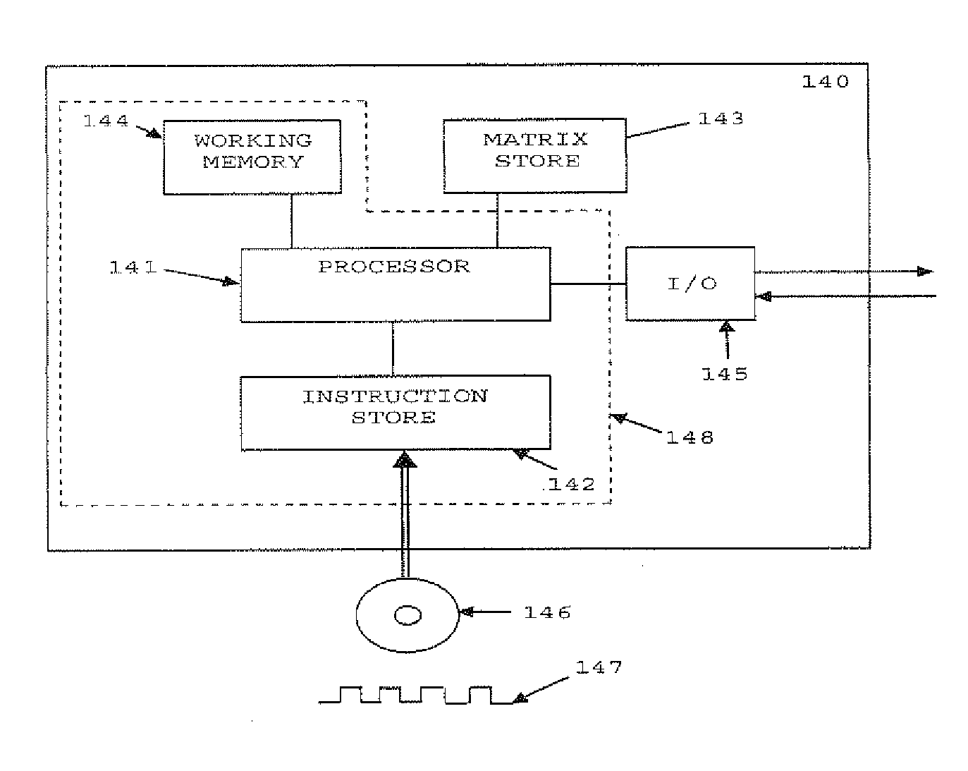
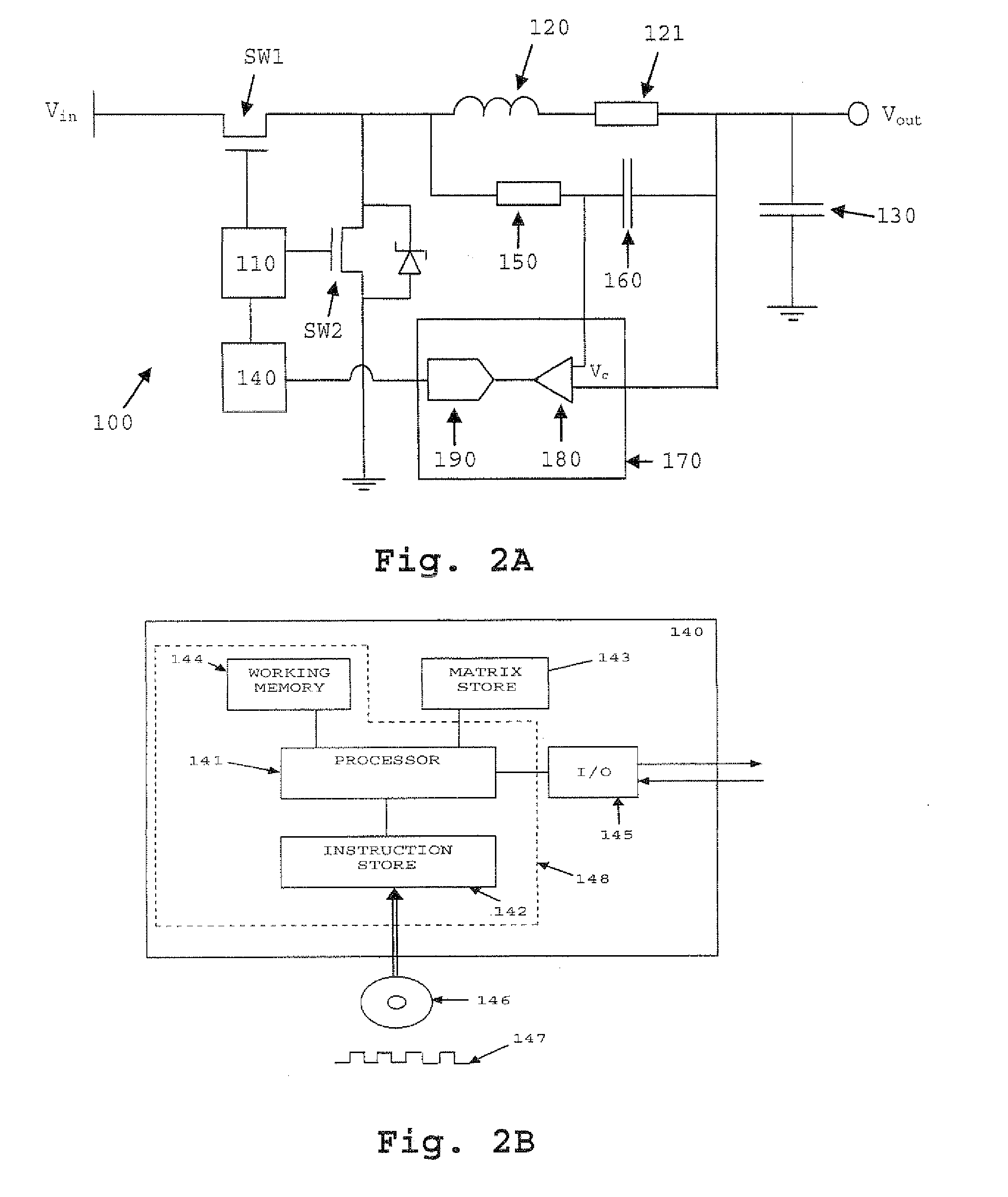
[0038]FIG. 2A is a schematic of a switched mode DC / DC power supply 100 according to a first embodiment of the present invention. The power supply includes transistors SW1 and SW2 which are preferably power MOSFETs. The switching of transistors SW1 and SW2 is controlled by a PWM controller 110. The PWM controller 110 is configured to apply voltage pulses preferably at a frequency in the range between 20 kHz and 1 MHz to the gates of transistors SW1 and SW2, and to vary the duty cycle of the switching in response to a feedback signal received from a signal processing unit 140. Alternatively, instead of the PWM controller 110 a frequency-modulating controller (not shown) can be used, which modulates the frequency at which pulses of a fixed duration are generated. The source terminal of transistor SW1 is connected to a DC voltage line at Vin while the source of transistor SW2 is connected to a reference point such as earth. The drain of each transistor is connected to an output filter, ...
PUM
 Abstract
Description
Claims
Application Information
 - R&D
- Intellectual Property
- Life Sciences
- Materials
- Tech Scout
- Unparalleled Data Quality
- Higher Quality Content
- 60% Fewer Hallucinations
Browse by: Latest US Patents, China's latest patents, Technical Efficacy Thesaurus, Application Domain, Technology Topic, Popular Technical Reports.
© 2025 PatSnap. All rights reserved.Legal|Privacy policy|Modern Slavery Act Transparency Statement|Sitemap|About US| Contact US: help@patsnap.com


