Eureka AIR delivers breakthrough ideas for toughest innovation challenges, trusted by R&D personnel around the world.

Device for filtering lubricants of a wind turbine transmission

a technology for filtering lubricants and wind turbines, which is applied in the direction of lubricant mounting/connection, machines/engines, gearing details, etc., can solve the problems of crack propagation and fracture of material, wind turbine transmissions are exposed to adverse effects of water, and the maintenance cost of hydrocarbon adsorbers is low

Inactive Publication Date: 2012-04-05
SIEMENS AG
View PDF0 Cites 0 Cited by
  • Summary
  • Abstract
  • Description
  • Claims
  • Application Information

AI Technical Summary

Benefits of technology

[0011]An object of the claimed invention is to provide an improved device for filtering lubricants of a wind turbine transmission, in which the clogging of the filter material due to water content is reduced in comparison with known filter devices of this type.
[0018]This allows longer filter change intervals. In addition, the maintenance costs for the hydrocarbon adsorber are low because the adsorber can be regenerated and the adsorber material itself is inexpensive.

Problems solved by technology

Wind turbine transmissions are exposed to adverse effects of water.
The water can attack both the transmission and the lubricants.
This can result in crack propagation and fractures in the material.
In addition, both free and absorbed water result in increased aggressive acid potential and hence in corrosion and pitting on the surfaces.
The removal of iron oxides can likewise result in the formation of fractures.
Furthermore, water has a negative effect on the properties of the transmission lubricants.
If water and metal particles, e.g. wear debris, are present in the lubricating oil, antioxidants are expended more rapidly and this again results in corrosion on the metal surfaces.
Further possible consequences include the formation of sludge and film, and uneven oil flow.
Water also reduces the efficiency of other additives, thereby promoting the formation of acid and sludge on the floor of the oil sump.
Other possible consequences include technical problems such as the formation of foam or microbial impurities in the oil, and a reduction in the stability of the oil film or a change in the viscosity of the oil.
The disadvantage here is that the pores of the filter material become clogged over time.
The changing of the filter material is demanding and expensive in this case, particularly in the case of wind power installations at sea, which are difficult to access.

Method used


Image

  • Device for filtering lubricants of a wind turbine transmission
  • Device for filtering lubricants of a wind turbine transmission
  • Device for filtering lubricants of a wind turbine transmission

Examples


Embodiment Construction

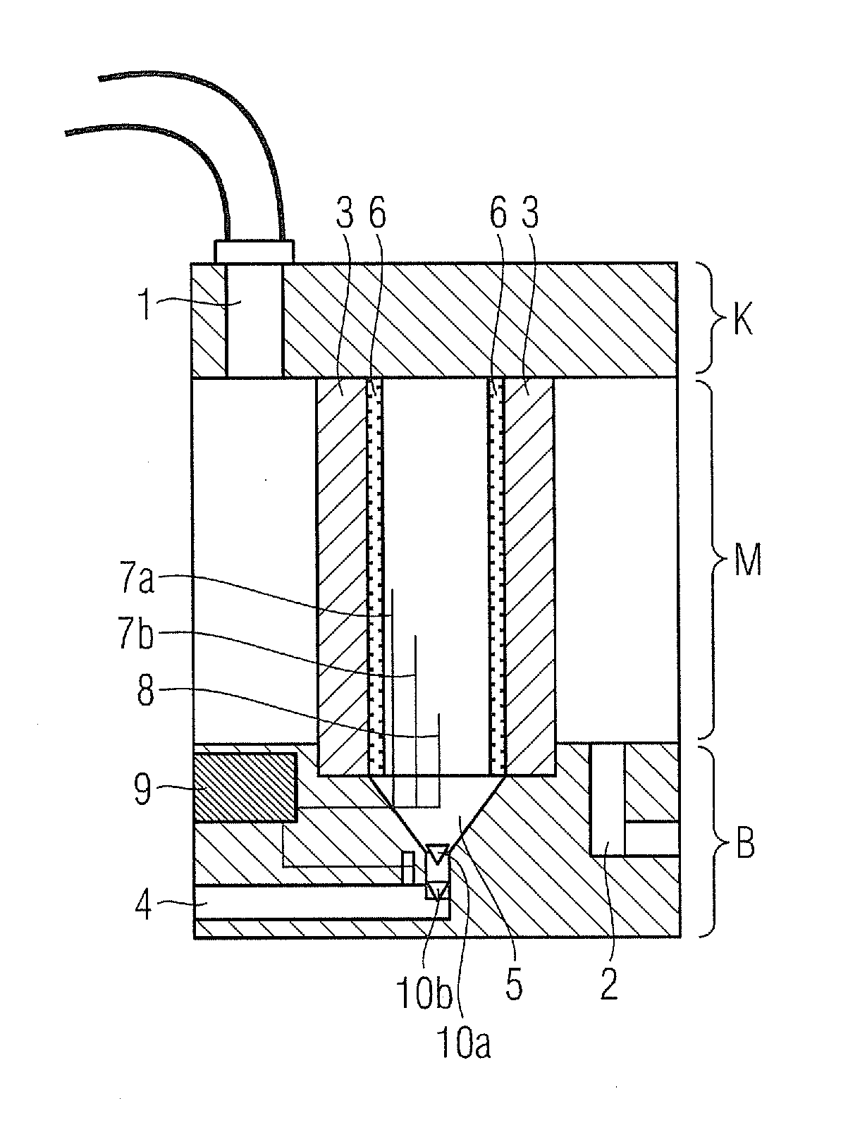
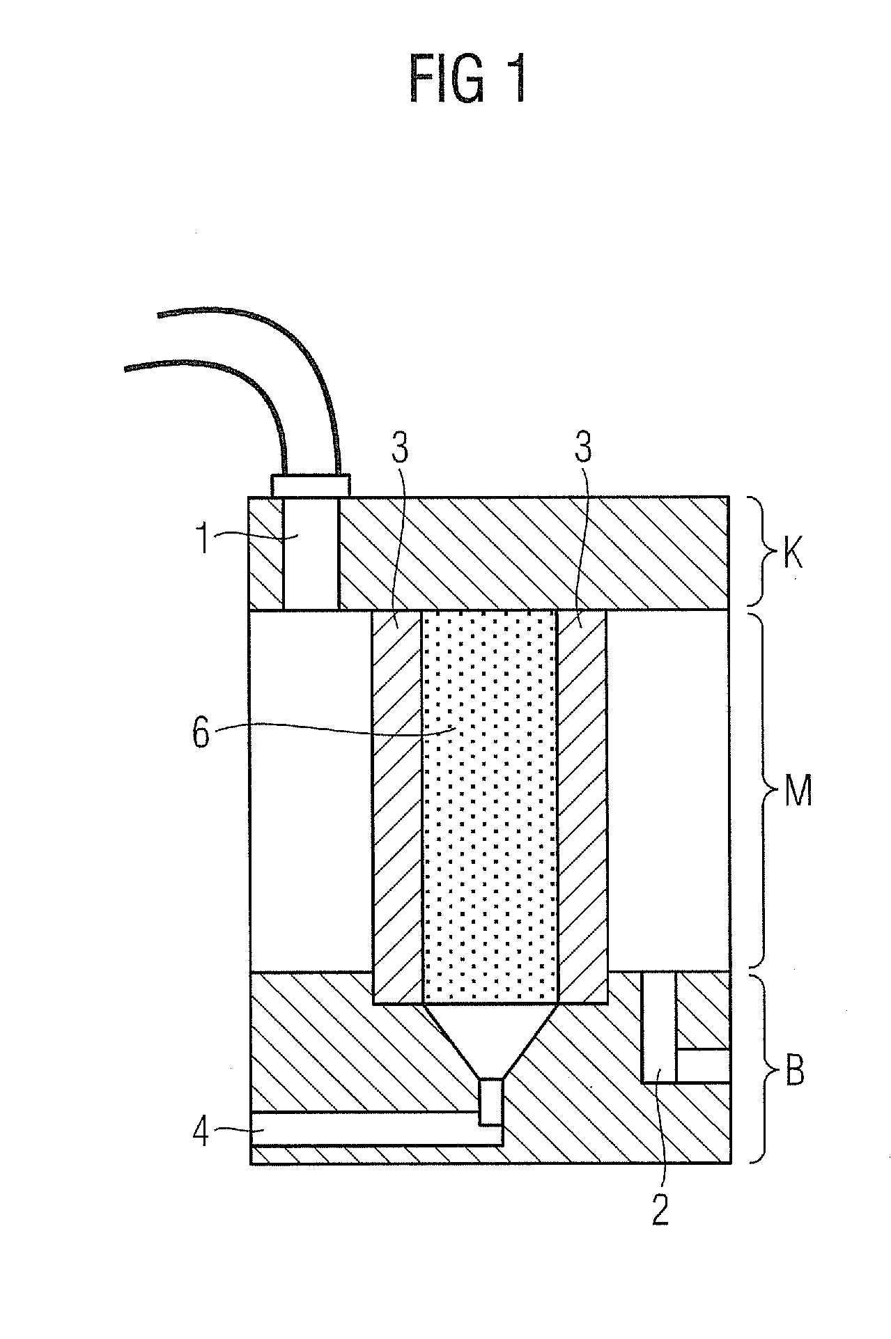
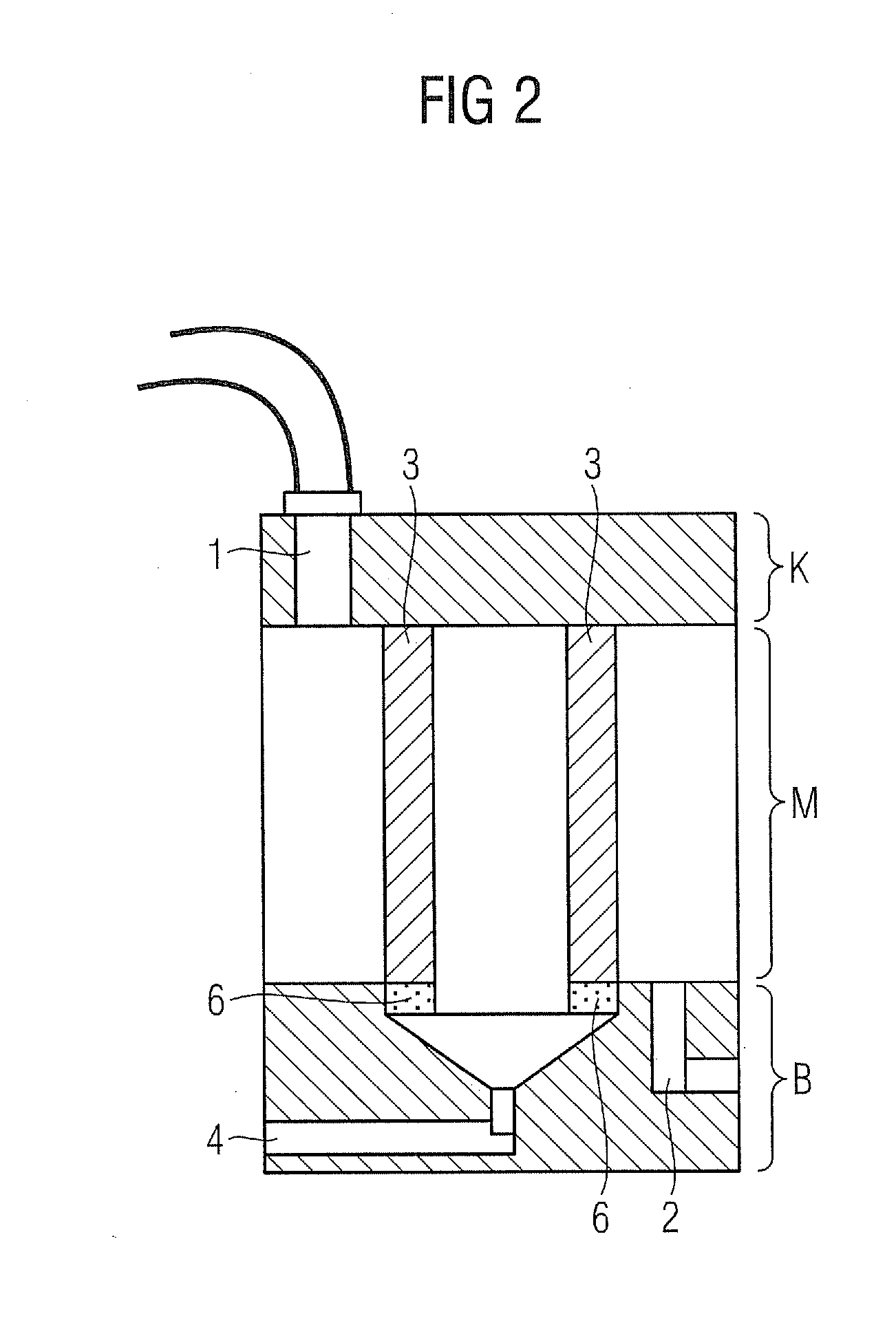
[0024]As shown in FIG. 1, the device according to the invention has a lubricant inlet (1), e.g. for transmission oil. The transmission oil that is to be filtered arrives in the device via an oil inlet connection piece or manifold (1) and is carried through the device to the oil outlet (2), which is situated downstream at the lower end of the device.

[0025]The transmission oil is preferably carried though the filter device under pressure from a pump, but alternatively can flow through the device without pressure and solely due to gravity by virtue of the relative arrangement of oil inlet (1) and oil outlet (2).

[0026]A filter element (3) is arranged between the oil inlet (1) and the oil outlet (2). The filter element (3) is designed to separate water from transmission oil or other lubricants. For this purpose, the filter element (3) features a hydrophobic fibrous braided fabric and / or a hydrophobic mesh-type material.

[0027]The filter element (3) is designed in the shape of a cylinder a...


PUM


Abstract

A device for filtering lubricants of a wind turbine transmission includes a lubricant inlet and a lubricant outlet. Lubricants of the wind turbine transmission are carried from the lubricant inlet to the lubricant outlet. The device further includes a filter element which is arranged between the lubricant inlet and the lubricant outlet. The filter element is designed such that water is separated from the lubricants by the filter element. A water outlet is connected to the filter element, such that the separated water can be drained out of the device. A hydrocarbon adsorber is arranged between the filter element and the water outlet, such that it purifies the separated water of hydrocarbons.

Description

CROSS REFERENCE TO RELATED APPLICATIONS[0001]This application claims priority of German Patent Application No. 10 2010 041 750.5 filed Sep. 30, 2010, which is incorporated by reference herein in its entirety.FIELD OF INVENTION[0002]The present invention relates to a device for filtering lubricants of a wind turbine transmission, a wind turbine comprising such a device, and a method for filtering lubricants of a wind turbine transmission.BACKGROUND OF INVENTION[0003]Wind turbine transmissions are exposed to adverse effects of water. The water can attack both the transmission and the lubricants.[0004]Water occurs in the transmission in the form of so-called “free water”, in absorbed form or as part of an emulsion. When separating water by means of electrolysis, hydrogen is released. This can result in crack propagation and fractures in the material. In addition, both free and absorbed water result in increased aggressive acid potential and hence in corrosion and pitting on the surface...

Claims


Application Information

Patent Timeline
Patent Type & Authority Applications(United States)
IPC IPC(8): F01M11/03
CPCF03D11/0008F05B2260/63Y02E10/722F16H57/0404F05B2260/98F03D80/70Y02E10/72
Inventor BRASSEUR, MICHAELAWOHLLEB, MATTHIAS
Owner SIEMENS AG
Why Eureka
Eureka Blog
Learn More