
Impulse sealer including ceramic-covered heater

a technology of impulsive heat sealing and ceramics, which is applied in the direction of packaging foodstuffs, packaged goods, other domestic articles, etc., can solve the problems of thermal weakness of film, user's hand touching the heater wire and receiving electric shock, and electric shock may occur

Inactive Publication Date: 2012-04-05
SAKAMOTO ATSUNOBU +2
View PDF12 Cites 25 Cited by
  • Summary
  • Abstract
  • Description
  • Claims
  • Application Information

AI Technical Summary

Benefits of technology

[0008]According to some illustrative and non-limiting embodiments, a heat sealer includes a press mechanism, a heater attached to a jaw of the press mechanism, and an electric power circuit connected to the heater, the electric power circuit receiving electric power from an external power source. In some examples, the heat sealer clamps and presses an object made of a thermoplastic resin by using the press mechanism, instantaneously heats the heater by passing a high electric current through the heater in a short time, melts the object, and cools and solidifies the object by interrupting the electric current. In some examples, the heater includes (a) a thin thermal-electrical insulator plate, (b) one or more heater wires, (c) a ceramic plate, (d) a thermal-electrical insulator, and (e) a thin release film. In some examples, the thin thermal-electrical insulator plate has an appropriate size and thickness, and is superposed on a heat dissipating base or on the jaw that also serves as the heat dissipating base, the heat dissipating base being made of a metal and disposed on the jaw of the press mechanism. In some examples, each heater wire is a thin metal resistor plate superposed on the thin thermal-electrical insulator plate, the heater wire including an electrode that is connected to the electric power circuit and a heat generating portion having a strip-like shape or a desired shape. In some examples, the ceramic plate (hereinafter referred to as a thermally conductive electrical insulator) is superposed on the heat generating portion, the thermally conductive electrical insulator having a flat surface that closely contacts the heat generating portion, the thermally conductive electrical insulator being an electrical insulator and having a thermal conductivity that is equal to or higher than that of alumina. In some examples, the thermal-electrical insulator covers exposed portions of the heater wires and the electrode, the thermal-electrical insulator surrounding a part of the exposed portions located around the thermally conductive electrical insulator so that the part is electrically and thermally insulated and surrounding a remaining part of the exposed portions so that the remaining part is at least electrically insulated. In some examples, the thin release film is superposed constantly or as necessary on the thermally conductive electrical insulator with or without a gap therebetween. In some examples, the elements of the heater described in (a) to (e) are made to closely contact each other and fixed at necessary positions by using an adhesive, a sticky agent, or a physical method.

Problems solved by technology

When an electric current is passed through the heater wire, an electric shock may occur.
However, if the zigzag-shaped portion of the heater wire is stretched or if an end of a broken heater wire protrudes, part of the heater wire may be exposed to the outside from the mouth of the press mechanism even if the press mechanism is closed.
If a switch is pressed and the heater wire is energized in this state, a user's hand may contact the heater wire and receive an electric shock.
However, the film is thermally weak.
The heater wire is frequently overheated because air, which is a thermal insulator, enters such parts and inflates from below the film.
As a result, within several months or so, the film becomes burned and charred, and the film is removed from the heater wire when replacing fluoropolymer tape affixed to the film.
Then, the high-temperature is related to material degradation such as 475° C. embrittlement of an iron-chromium alloy from which the heater wire is made, so that using the film is not an effective measure.
However, a film having a thickness of 60 micrometers, which is the smallest available thickness, considerably impedes heat transfer.
Therefore, a sealer using a thick film does not have practical utility.

Method used


Image

  • Impulse sealer including ceramic-covered heater
  • Impulse sealer including ceramic-covered heater
  • Impulse sealer including ceramic-covered heater

Examples


first embodiment

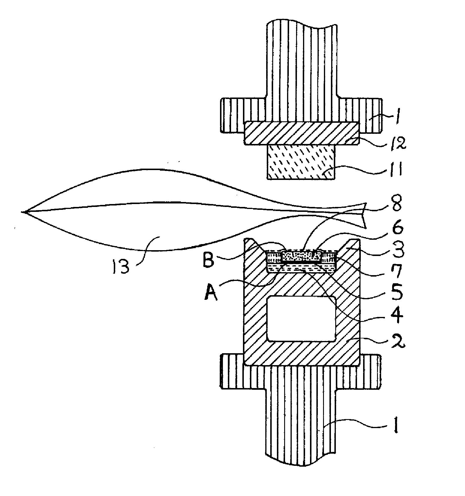
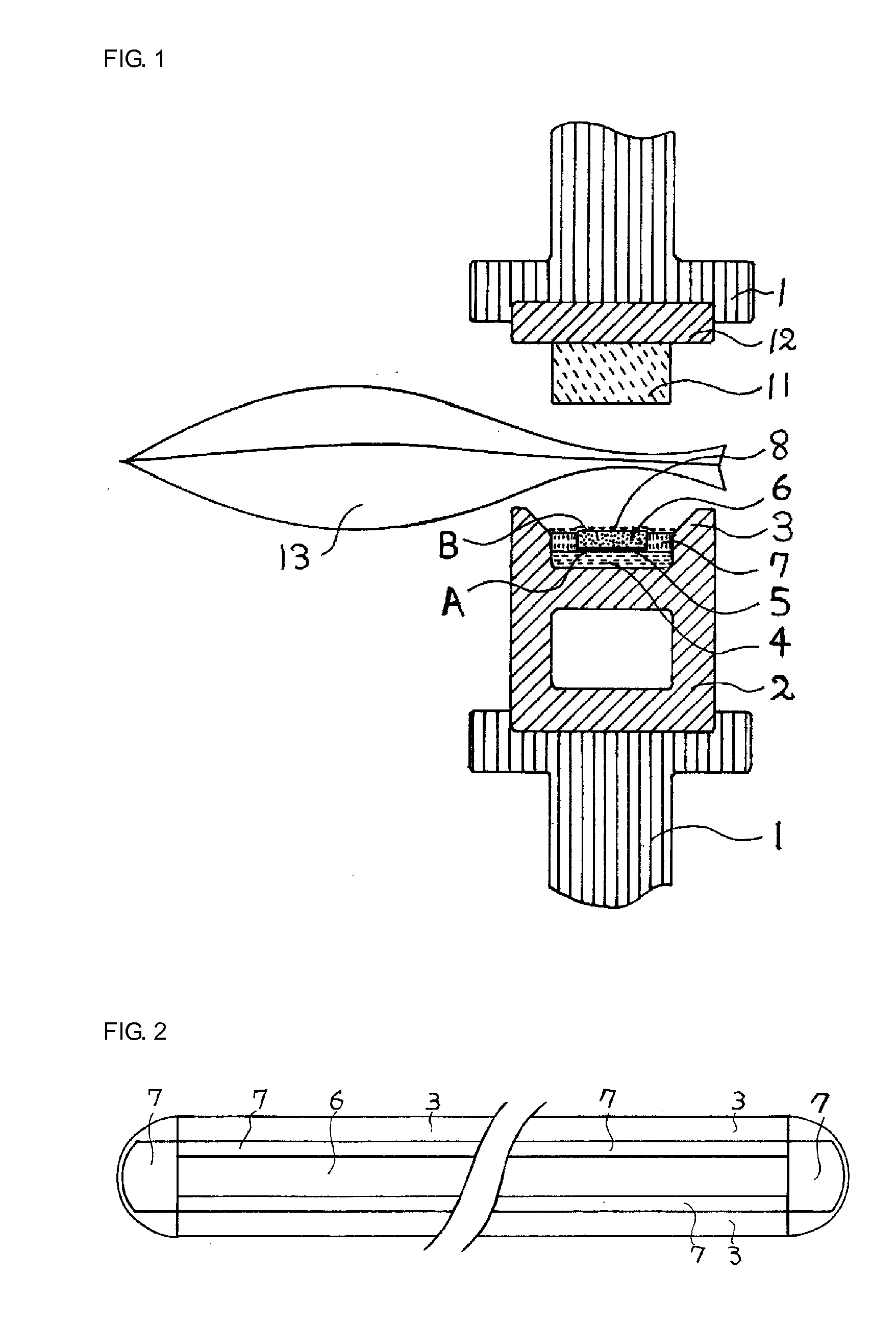
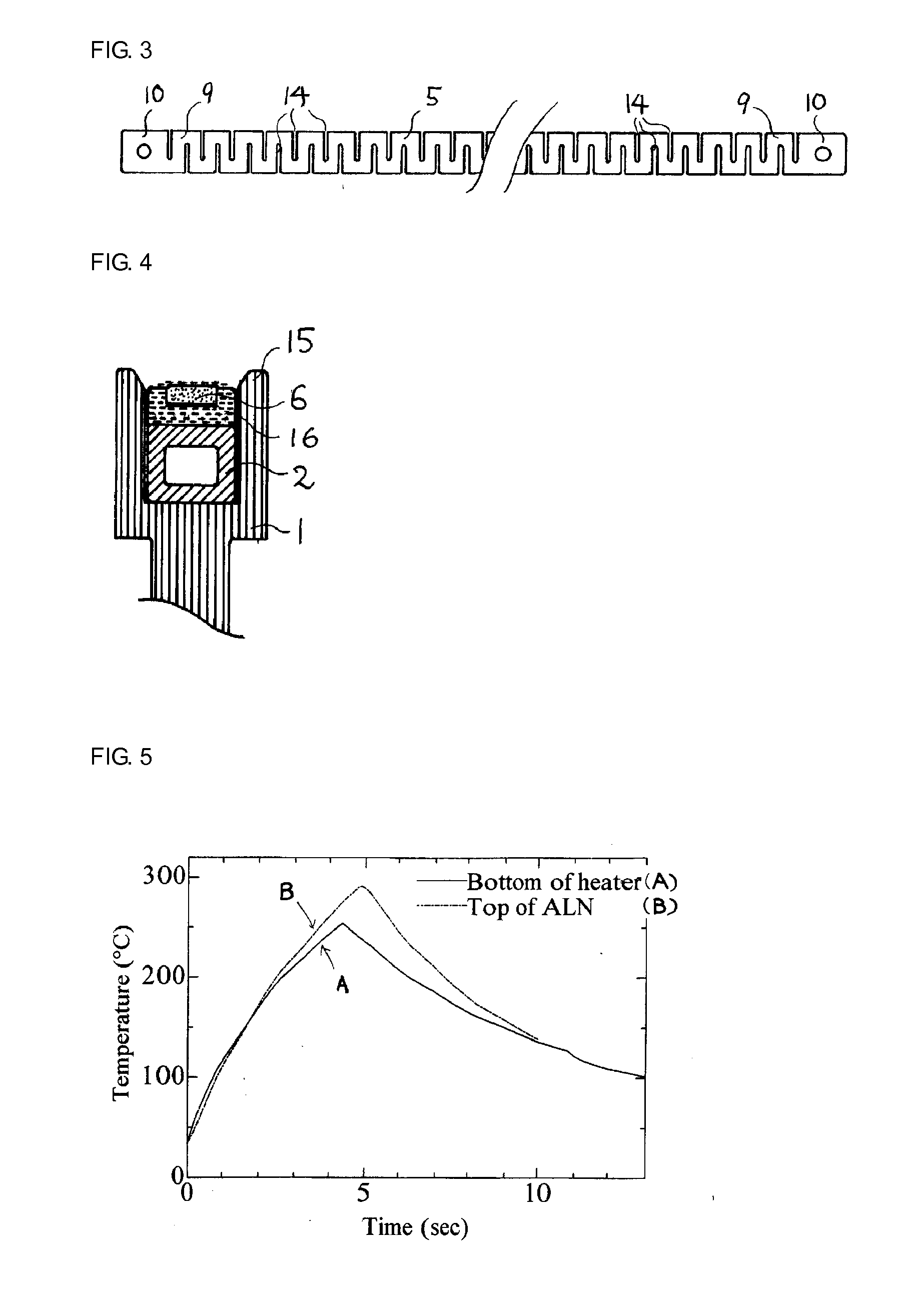
[0031]FIG. 1 is sectional view illustrating an example of a heater and a press mechanism in which the heater is mounted according to the first embodiment. A heat dissipating base 2, which is an extruded aluminium pipe having a rectangular cross section, is fixed to one of jaws 1 (partially illustrated in FIG. 1) of the press mechanism. Ribs 3 having a height of 1.7 mm are formed at edges on both sides of the upper surface of the heat dissipating base 2. A piece of Sarcon tape 4 having a thickness of 0.45 mm is affixed to a part of the upper surface of the heat dissipating base 2 between the ribs 3. The piece of Sarcon tape 4 serves as a thermal-electrical insulator that insulates the heat dissipating base 2 from heat. (Sarcon tape, which is manufactured by Fuji Polymer Industries Corporation, is tape composed of a silicone rubber, a glass cloth, and aluminium nitride powder or alumina powder). A heater wire 5 having a zigzag shape is superposed on the piece of Sarcon tape 4. The hea...

second embodiment

[0049]As illustrated in FIG. 7, which is a sectional view, a heat die 18 made of aluminium nitride or aluminium is disposed on the thin aluminium nitride plate 6. The heat die 18 has a triangular cross section and, for example, has a height of 0.3 mm, a bottom surface having a width of 0.6 mm, and a length the same as that of the heater. A piece of fluoropolymer tape is applied to the heat die 18. Thus, temporary sealing and heat cutting can be performed. Because the heat die 18 is electrically insulated by the thin aluminium nitride plate, not only a ceramic but also a metal having a high heat conductivity can be used as the material of the heat die 18. One of the surfaces of the heat die 18 may have a three-dimensional shape suitable for the purpose of sealing. The heater can be used to seal an object that is too thick to be sealed by using existing sealers, such as a vinyl tube for blood transfusion. Moreover, for example, a date or the like can be stamped on an object while seal...

third embodiment

[0051]FIG. 9 is a sectional view of the heat dissipating base 2 illustrated in FIG. 1 and a heater disposed on the heat dissipating base 2. A flat plate 20 made of Invar (a nickel steel alloy) is disposed between the thin aluminium nitride plate 6 and the piece of fluoropolymer tape 8. The flat plate 20 has a thickness of 0.1 mm, a width of 2 mm, and a length the same as that of the thin aluminium nitride plate 6. The flat plate 20, the thin aluminium nitride plate 6, and the pieces of glass cloth tape 7 on both sides are fixed with an adhesive. The thermal expansion coefficient of Invar is substantially equal to zero at room temperature, but the thermal expansion coefficient is higher at a temperature of about 150° C. Therefore, if a silicone adhesive is appropriately used, the adhesive can follow the displacement between the flat plate 20 and the thin aluminium nitride plate 6. The thermal expansion coefficient of the flat plate 20 can be made the same as that of the thin aluminiu...


PUM

PropertyMeasurementUnit
widthaaaaaaaaaa
lengthaaaaaaaaaa
currentaaaaaaaaaa

Abstract

A heat sealer includes a press mechanism, a heater, and an electric power circuit. The heater includes: a thin thermal-electrical insulator plate superposed on a heat dissipating base or on a jaw of the press mechanism; one or more heater wires each of which is a thin metal resistor plate superposed on the thin thermal-electrical insulator plate, each heater wire including an electrode and a heat generating portion; a thermally conductive electrical insulator superposed on the heat generating portion, the thermally conductive electrical insulator being an electrical insulator and having a thermal conductivity that is equal to or higher than that of alumina; a thermal-electrical insulator that covers exposed portions of the heater wires and the electrode; and a thin release film superposed on the thermally conductive electrical insulator. The elements of the heater are made to closely contact each other and fixed by using an adhesive or the like.

Description

BACKGROUND[0001]1. Field[0002]The present disclosure relates to an impulse heat sealer, and in particular, to a heater.[0003]2. Description of the Related Art[0004]Existing impulse heat sealers including a heater wire having, for example, a length of 20 cm and a width of 2 mm, require a low voltage and a high current such as 20 V and 10 A. Therefore, a heavy transformer is necessary to use such an impulse heat sealer with commercial electric power at 100 V. The inventors have improved an existing strip-shaped heater wire by cutting narrow slits into the wire from both sides of the wire, thereby forming a zigzag shape having a small and uniform width, which is electrically narrow and long. As a result, a high voltage and a low current such as 100 V and 2 A can be used, and an impulse heat sealer can be directly connected to the commercial electric power. Thus, a heavy transformer is not necessary, and a lightweight and energy-saving impulse heat sealer is realized. (See Japanese Pate...

Claims


Application Information

Patent Timeline
Patent Type & Authority Applications(United States)
IPC IPC(8): H05B1/00
CPCB29C65/224B29C66/961B29C65/743B29C66/0044B29C66/1122B29C66/225B29C66/229B29C66/43121B29C66/71B29C66/73921B29C66/81457B29C66/8167B29C66/81821B29C66/81871B29C66/83221B29C66/849B29C66/919B29C66/91951B29C65/38B29C66/91212B29C66/8122B29C66/81419B29C66/91231B65B29/02B65B51/146B29C66/91421B29C66/91443B29C66/91641B29C66/91655B29K2023/06B29K2909/02B29C66/81261B29C66/81831B29C66/8185B29L2031/7122B29L2031/7128B65B29/028B29K2909/04B29K2883/00
Inventor SAKAMOTO, ATSUNOBUSAKAMOTO, KAZUKOYAMADA, KAZUKUNI
Owner SAKAMOTO ATSUNOBU
Learn More