Integrated pressure vessels for vehicular applications

a technology for vehicular applications and pressure vessels, applied in the direction of electrochemical generators, transportation items, containers, etc., can solve the problems of assembly damage, especially vessels, and achieve the effects of enhanced connectivity, enhanced resistance to deformation defined in the frame, and enhanced overall moment of inertia of the fram

a technology for vehicular applications and pressure vessels, applied in the direction of electrochemical generators, transportation items, containers, etc., can solve the problems of assembly damage, especially vessels, and achieve the effects of enhanced connectivity, enhanced resistance to deformation defined in the frame, and enhanced overall moment of inertia of the fram

US20120080875A1Active Publication Date: 2012-04-05GM GLOBAL TECH OPERATIONS LLC

Image

  • Integrated pressure vessels for vehicular applications
  • Integrated pressure vessels for vehicular applications
  • Integrated pressure vessels for vehicular applications

Examples


Embodiment Construction

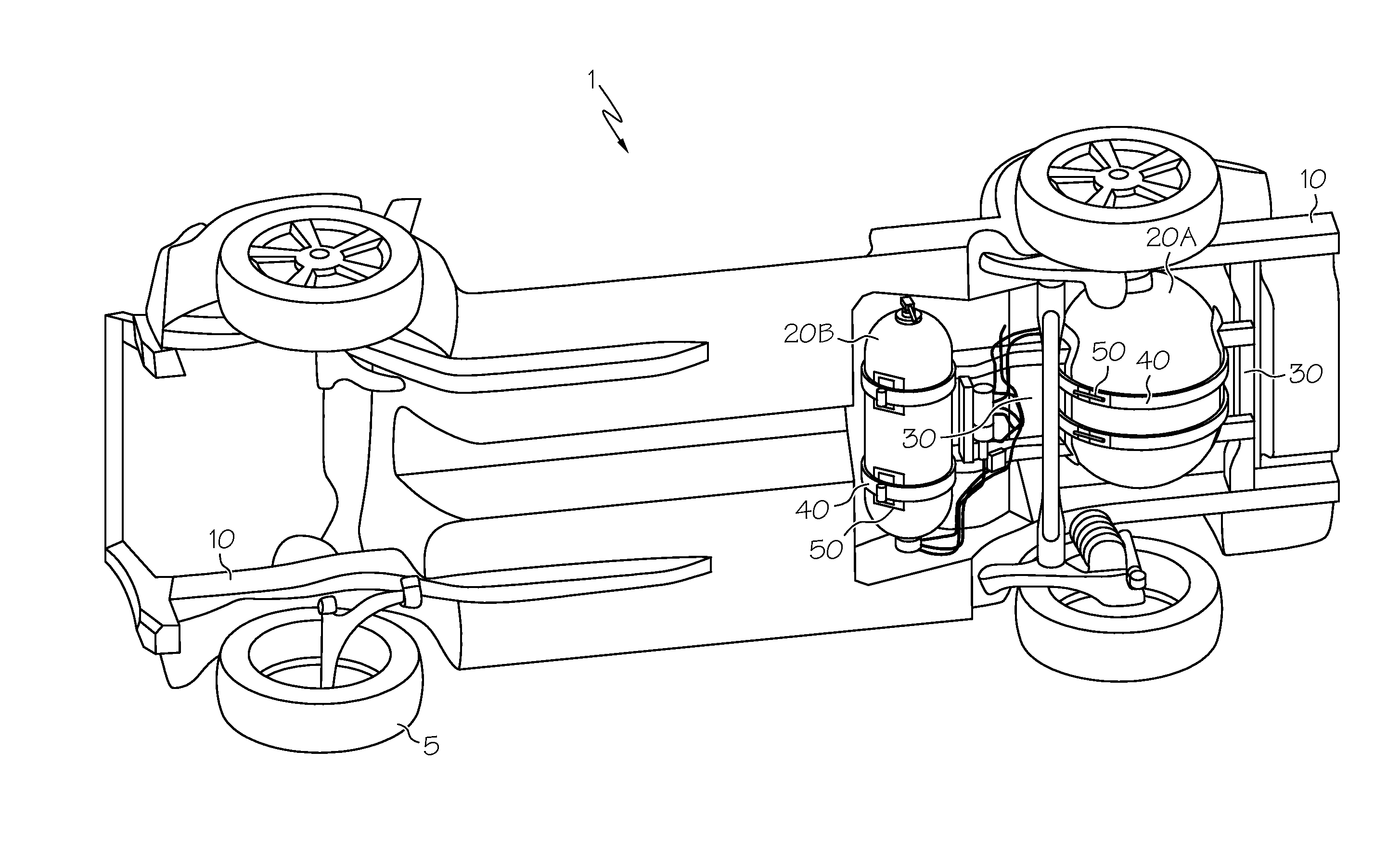
[0024]Referring first to FIG. 1, a tank-mounting arrangement for a high pressure hydrogen storage tank system according to the prior art shows a vehicular chassis 1 with four wheels 5 mounted to a frame 10 made from longitudinally-oriented sections of tubular steel. Frame 10 provides the primary structural support for most of the remaining components of chassis 1, as well as the body (not shown) of the vehicle; much of the load-bearing capability inherent in frame 10 is due to its size, shape, material choice and related design attributes that are understood by those skilled in the art. A fuel cell-based motor (not shown) could be situated in any convenient location within the chassis 1, for example, between the front wheels 5 shown on the left side of the figure. Gaseous fuel is stored in one or more tanks 20. In the version shown, a pair of such tanks includes a larger main tank 20A and a smaller secondary tank 20B. Both tanks 20A, 20B are secured to chassis 1 by crossbars 30, str...


PUM

PropertyMeasurementUnit
lengthaaaaaaaaaa
lengthaaaaaaaaaa
lengthaaaaaaaaaa

Abstract

A fuel vessel assembly for a fuel cell-powered vehicle and a method of increasing the structural rigidity of a fuel cell-powered vehicle. A vessel for storage of hydrogen or related fuel cell-compatible fuel is rigidly attachable to a vehicular frame or related load-bearing structure through one or more shells that extend from the vessel. Loads imparted to one or more of the shell, vessel frame are transmitted between them through the connection between the assembly and the frame such that a load-bearing capability inherent in the frame is enhanced by the assembly.

Description

BACKGROUND OF THE INVENTION[0001]The present invention relates generally to devices and methods for placing high pressure storage vessels into a vehicle structure, and more particularly to a way to integrate a vessel for storing a pressurized fuel source on a vehicle that employs a fuel cell-based architecture as a source of motive power such that the vessel increases the load-bearing capability of the vehicle.[0002]In a typical fuel cell system, hydrogen or a hydrogen-rich gas is supplied through a flowpath to a catalytic electrode on one side of a fuel cell while oxygen (such as in the form of atmospheric oxygen) is supplied through a separate flowpath to another catalytic electrode situated elsewhere on the fuel cell. The electrochemical conversion of the elemental hydrogen and oxygen into hydrogen and oxygen ions on these electrodes (called anodes and cathodes, respectively) allows dissociated electrons to be routed through an electrically-conductive direct current (DC) circuit ...

Claims


Application Information

Patent Timeline
05 Apr 2012
Publication
US20120080875A1
IPC
B60K15/03
CPC
B60K15/07; Y02E60/321; F17C2201/0109; F17C2201/035; F17C2201/056; F17C2203/0617; F17C2203/0619; F17C2203/0639
Inventors
SCHULTHEIS, VALENTIN; SCHUTZ, THORSTEN