High Fill-Factor Electronic Beam Steerer

a phased array and electronic technology, applied in the direction of optics, instruments, optical elements, etc., can solve the problems of inability to use dfcls, and inability to achieve dfcls in a usable form, so as to reduce the motion of the mode, reduce the mechanical motion, and be more robust

Inactive Publication Date: 2012-04-05
RAYTHEON CO
View PDF5 Cites 27 Cited by
  • Summary
  • Abstract
  • Description
  • Claims
  • Application Information

AI Technical Summary

Benefits of technology

[0026]Accordingly, an array of phase-locked sub-apertures with adaptive correction of phase distortions incorporated directly into each sub-aperture (such as an APPLE system) will perform better with FSOPAs replacing a PZT fiber actuator (it should be noted that one FSOPA is needed for each dimension.)
[0027]Replacement of the PZT fiber actuator with a FSOPA eliminates mechanical motion in the APPLE system, resulting in a true non-mechanical, all-electronic system, and a much more robust system. The FSOPA will be at least as robust as a conventional OPA, which from tests is operable to hundreds of g's.
[0028]Furthermore, one possible issue with the current APPLE system is the demonstrated presence of higher order modes in the over-moded delivery fiber. These modes move around within the fiber core when the fiber is bent, change relative phases, and cause the output beam to both deform and move about, and that motion appears to preclude meeting the pointing accuracies desired. Replacement of the PZT fiber actuator with an FSOPA means that the fiber no longer needs to move and can be firmly anchored, presumably significantly reducing mode motions.
[0029]A fixed feed-point also allows the APPLE system to be fed by free-space lasers; thus, APPLE-type systems will no longer restricted to fiber lasers. Although fiber lasers are preferred in one sense because of their higher efficiencies, other laser types do offer other potential advantages, and new APPLE designs will allow tradeoffs to be made. As one example, a so-called Semi-Guiding High Aspect Ratio Core (SHARC) laser under development at Raytheon Space and Airborne Systems (SAS), El Segundo, Calif. 90245, USA offers an alternate path to mitigation of stimulated Brillioun scatter (SBS) because the effective core size is much larger than even the over-moded 25 micron core fibers currently used in APPLE. If the current SBS mitigation approach taken by RIFL (phase modulation at several GHz) proves to be incompatible with the APPLE control systems, SHARC offers a ready solution. It is compact and relatively high efficiency (25% wall plug efficiency predicted). It also offers prospects of operating at higher output powers (10 kW) than is predicted for single-mode fiber lasers (3-5 kW), meaning that the per sub-aperture power of an APPLE system would be limited by the damage levels of the APPLEt components rather than the fiber lasers. It is believed to be desirable to use as high power as possible per subaperture in order to reduce (or ideally minimize) the number of APPLEts needed to scale an array to desired power levels. The SHARC laser offers that prospect, and the APPLE architecture described herein makes the use of a SHARC laser feasible.
[0030]It has also been recognized that wide-angle electronic beamsteering systems requiring use of multiple apertures are useful for high-power directed-energy weapon (DEW) applications. For these systems, high fill factor, high throughput, and high scan speed are all needed. Here “fill factor” refers to the fraction of the face area of the composite aperture which is actually within the emitting areas of the individual apertures as opposed to non-emitting areas given over to support structure. High areal fill factor is important for maintaining a compact and high-efficiency beam on the distant target and is directly enabled by the architecture disclosed herein.
[0031]In accordance with the present invention, elimination of areal overhead of zone-fill OPAs at the exit aperture can be achieved by moving them internally where the beam is smaller and there is room around it for the overhead. Also, polarization gratings (PGs), electrically controlled rather than angle-addressed can be used to allow transmission of steerable beams through them. Also at least one very fast, dual-frequency liquid-crystal-(DFLC-) based, OPA pair can be implemented for fast scanning.

Problems solved by technology

Also, it is believed that such voltage levels are not compatible with high density integrated circuits and thus use of 200V driving signals is currently considered impractical for an OPA for which thousands of electrodes typically must be addressed.
While it is considered feasible to develop DFLCs with lower driving voltages, such DFCLs, however, do not yet exist in a usable form.

Method used


Image

  • High Fill-Factor Electronic Beam Steerer
  • High Fill-Factor Electronic Beam Steerer
  • High Fill-Factor Electronic Beam Steerer

Examples


Embodiment Construction

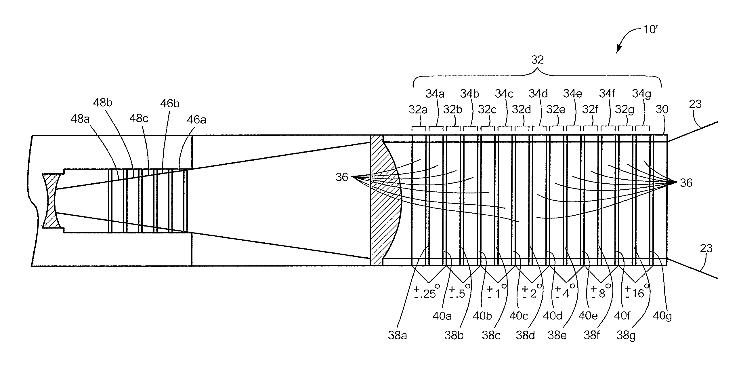
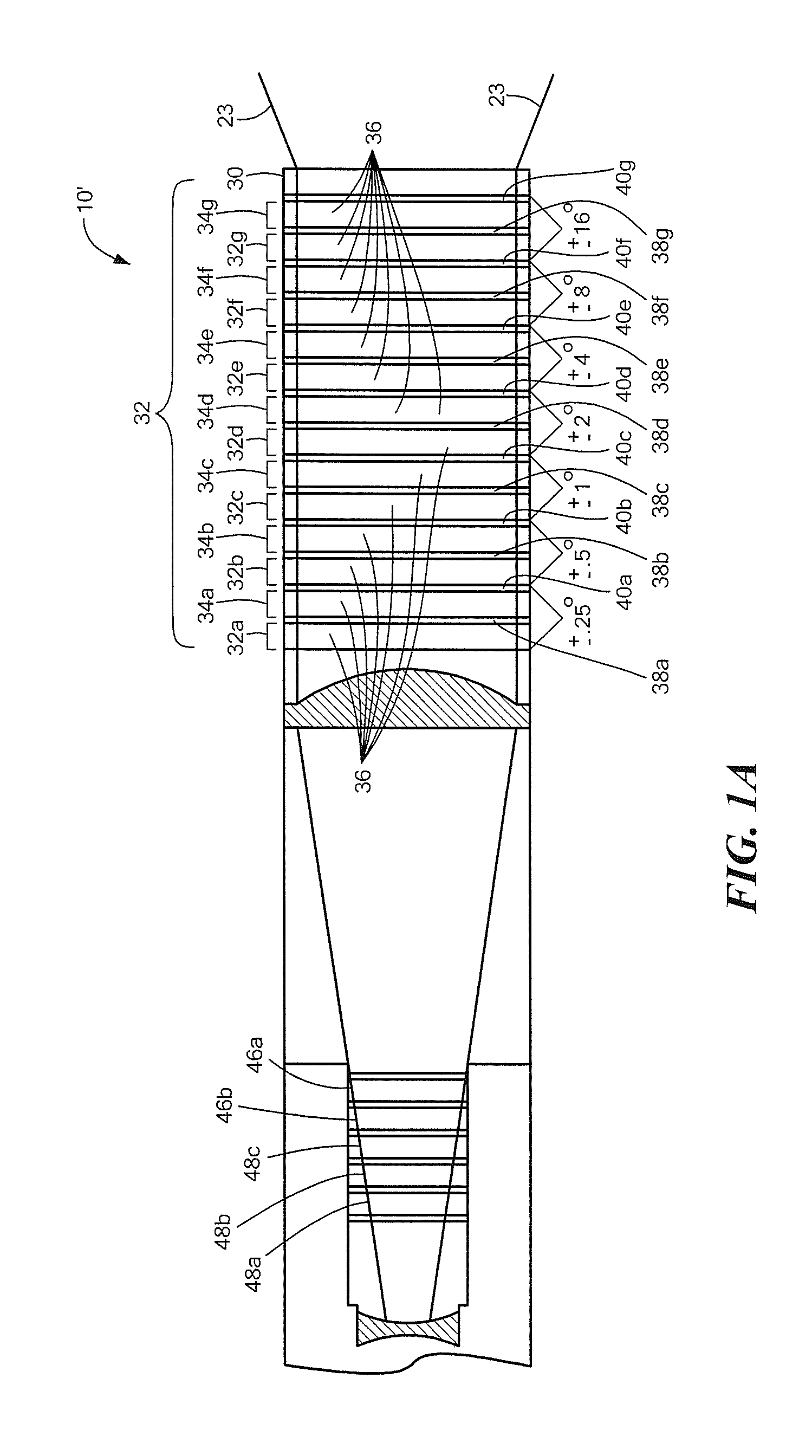
[0069]Described herein is the use of a fast-scanning optical phase array (FS OPA) within an electronic beam-steering-based aperture suitable for use in a system such as the Adaptive Photonically Phase-Locked Elements (APPLE) system, for example.

[0070]Also described is a stack of polarization gratings (PGs), each controlled by a liquid-crystal wave plate which may be used in the APPLE system.

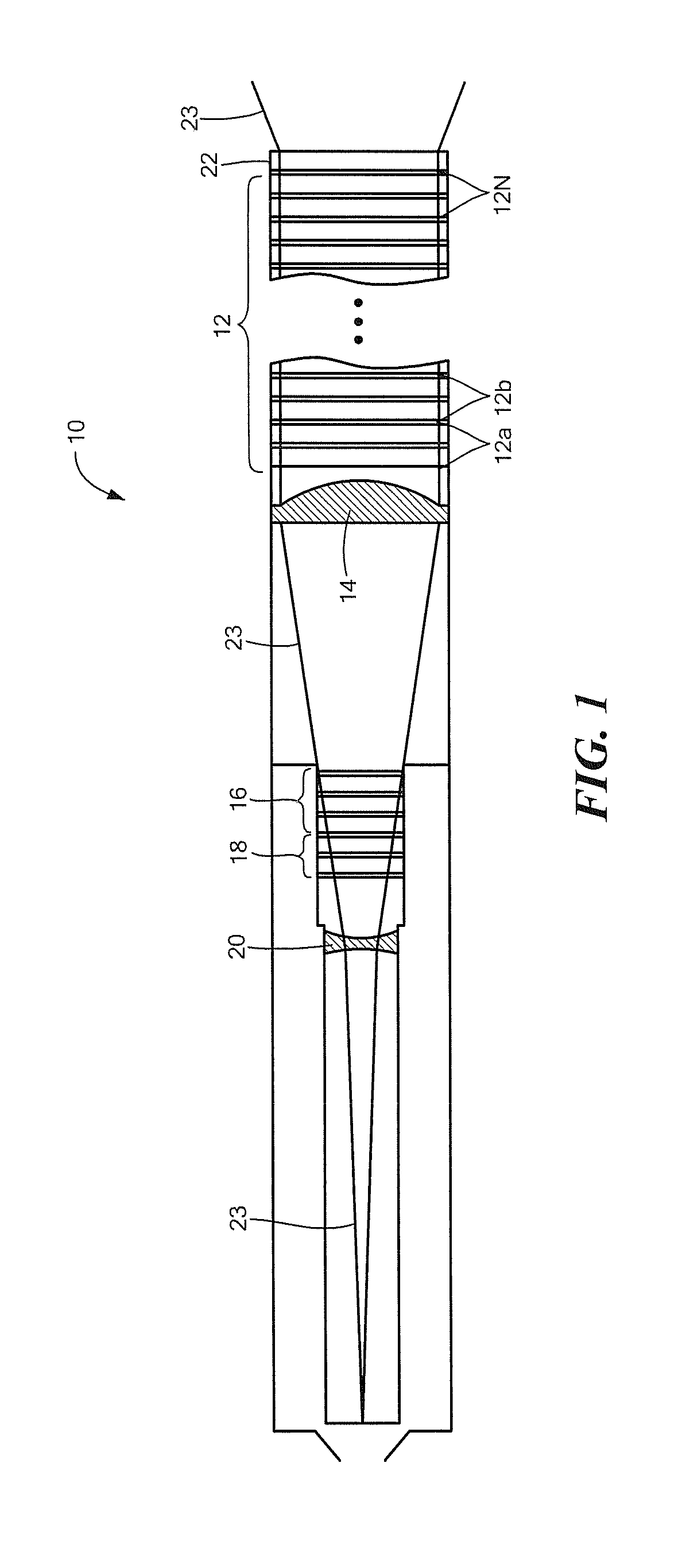
[0071]Before describing a fast-scanning optical phase array and a polarization grating architecture, some terminology is defined. As used herein, the term “aperture module” or more simply “aperture” to an optical train having one or more OPA devices, a polarization grating (PG) stack having at least some interleaved PG elements, an adaptive optics (AO) portion, coarse OPAs and one or more half wave plates. One exemplary aperture is a modified APPLE architecture referred to as an “APPLEt.” The terms “composite aperture,”“optical phased-array” or more simply “array” refer to a plurality of aperture...


PUM

PropertyMeasurementUnit
diameteraaaaaaaaaa
blocking timeaaaaaaaaaa
reset timeaaaaaaaaaa

Abstract

Described herein is the use of a fast-scanning optical phase array (OPA) within an electronic beam-steering-based aperture.

Description

FIELD OF THE INVENTION[0001]The system and techniques described herein relate generally to optical phased arrays and more particularly to steering a beam of an optical phased array.BACKGROUND OF THE INVENTION[0002]As is known in the art, there is a desire to provide an optical system capable of transmitting, receiving, and rapidly steering spatially phased optical energy and images, such a system having a composite aperture comprising multiple individual apertures (i.e., the composite aperture is an array of apertures) each of each should be transmissive.[0003]One such system which includes an array of small phase-locked apertures with adaptive correction of phase distortions incorporated directly into each aperture, is referred to as an Adaptive Photonics Phase-Locked Elements (APPLE). In the APPLE system, a conventional high-resolution adaptive optics (AO) system is replaced by an array of low-resolution “local” AO sub-systems (distributed AO) operating in parallel.[0004]The APPLE...

Claims


Application Information

Patent Timeline
Patent Type & Authority Applications(United States)
IPC IPC(8): G02F1/31
CPCG02F1/292G02F2001/133757G02F2203/24G02F2201/305G02F2201/16G02F1/133757
Inventor DORSCHNER, TERRY A.SMITH, IRL W.
Owner RAYTHEON CO
Why Eureka
Try Eureka