Cross-flow electrochemical batteries

a cross-flow electrochemical and battery technology, applied in the direction of secondary cell servicing/maintenance, cell components, electrolyte stream management, etc., can solve the problems of limiting the electric current in conventional cells and batteries, certain time-dependent processes, and not all faradaic surfaces exposed to electrolyte may contribute to cell charge or discharge current, etc., to achieve robust cfeb, promote ion mobility, and increase the mass transport of ions

Active Publication Date: 2012-04-05
GLOBAL ENERGY SCI CALIFORNIA
View PDF0 Cites 14 Cited by
  • Summary
  • Abstract
  • Description
  • Claims
  • Application Information

AI Technical Summary

Benefits of technology

[0065]It is therefore a first advantage of the present invention to provide a robust CFEB that provides greatly increased mass transport of ions by convection within the electrolyte and through porous electrodes.
[0066]A second advantage of the present invention is to provide a CFEB that uses incompressible forced convection—in addition to short path diffusion, dispersion or migration—as principal forces for promoting ion mobility.
[0067]A third advantage of the present invention is to provide a robust CFEB utilizing greatly increased active electrode areas exposed to flowing electrolytes in a compact cell volume.
[0068]A fourth advantage of the present invention is to provide a CFEB that does not have a tradeoff between electrode thickness and impedance.
[0069]A fifth advantage of this invention is to provide CFEB that create dynamic flows within electrolytes passing through open-cell, porous electrodes containing chemically active particles and surfaces to induce exceptionally high rates of mass transport to and from reduction-oxidation (redox) chemical reactions occurring at or on reactive surfaces.
[0070]A sixth advantage of this invention is to provide CFEB with low mass-transport-limiting and surface-limiting electrode characteristics and dynamic forced convective flow of electrolyte through electrodes that have very high surface area volumetric concentrations.

Problems solved by technology

However, not all of the faradaic surface exposed to electrolyte may contribute to cell charge or discharge current.
Both of these factors limit electric current in conventional cells and batteries.
This means that certain time-dependent processes, such as alternating current behavior and surge response, may not be accurately explained by the model.
These limitations of ion mobility under diffusion, dispersion and migration gradients are common to all prior art galvanic cells with porous electrodes.

Method used


Image

  • Cross-flow electrochemical batteries
  • Cross-flow electrochemical batteries
  • Cross-flow electrochemical batteries

Examples


first embodiment

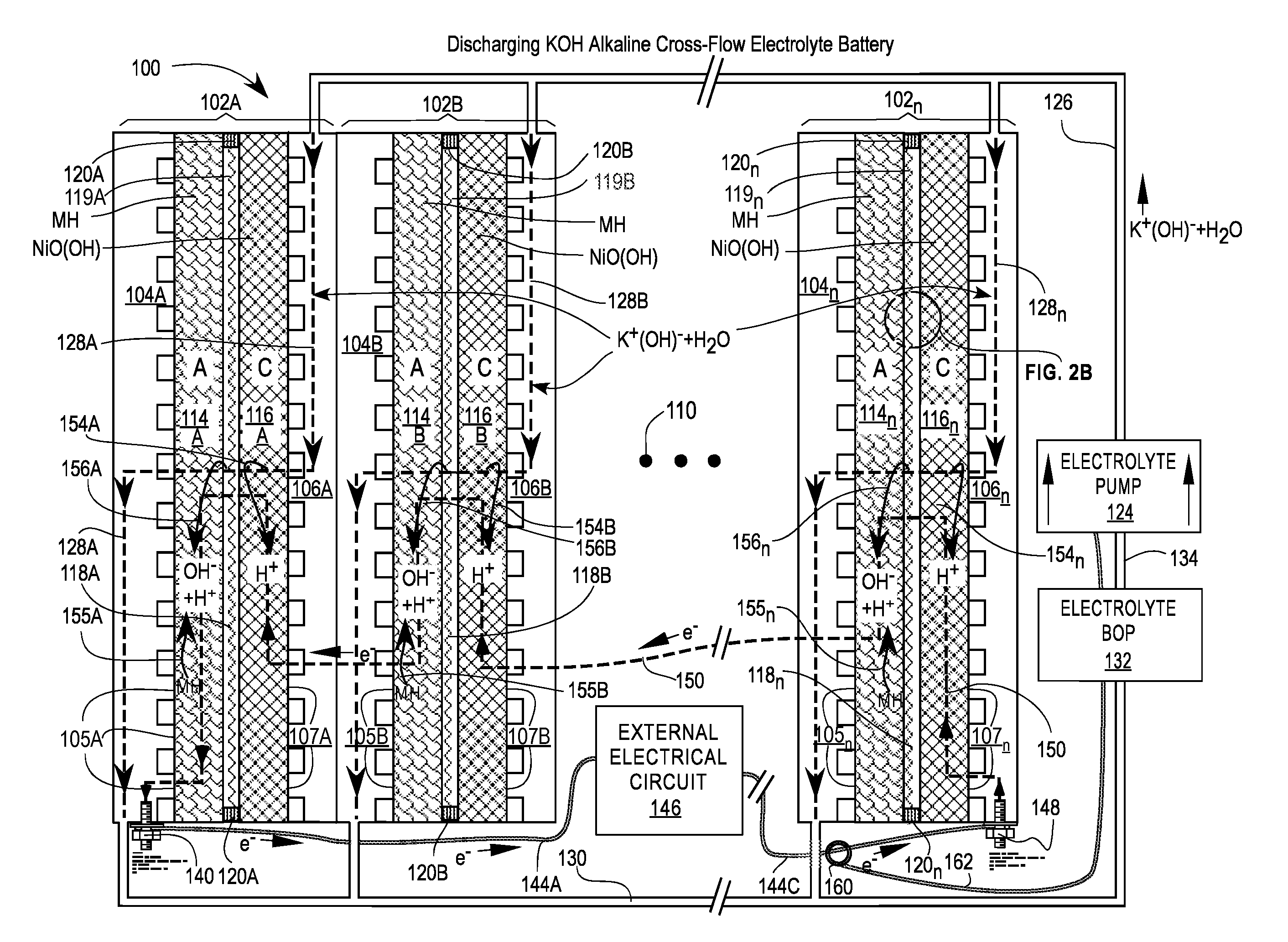
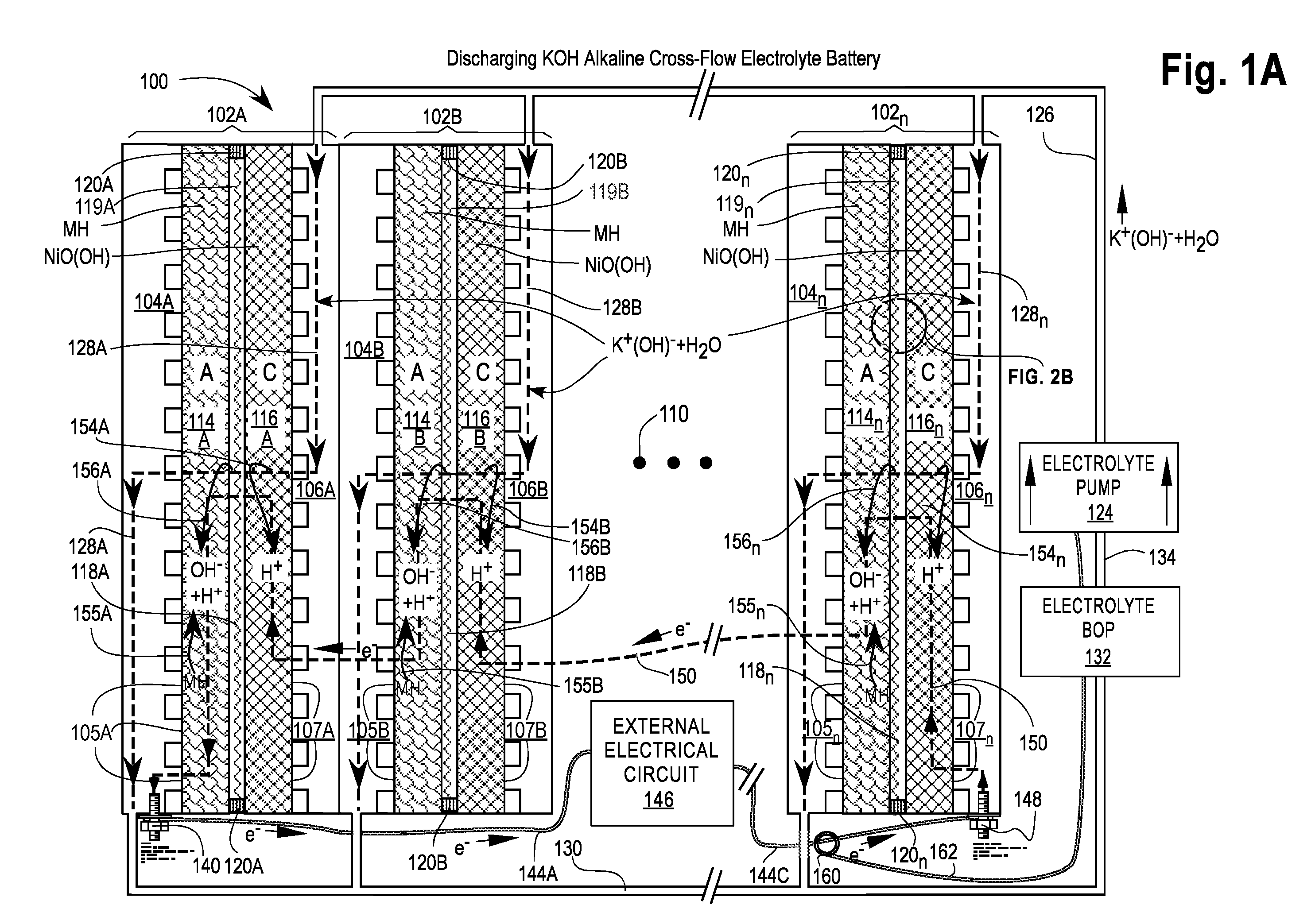
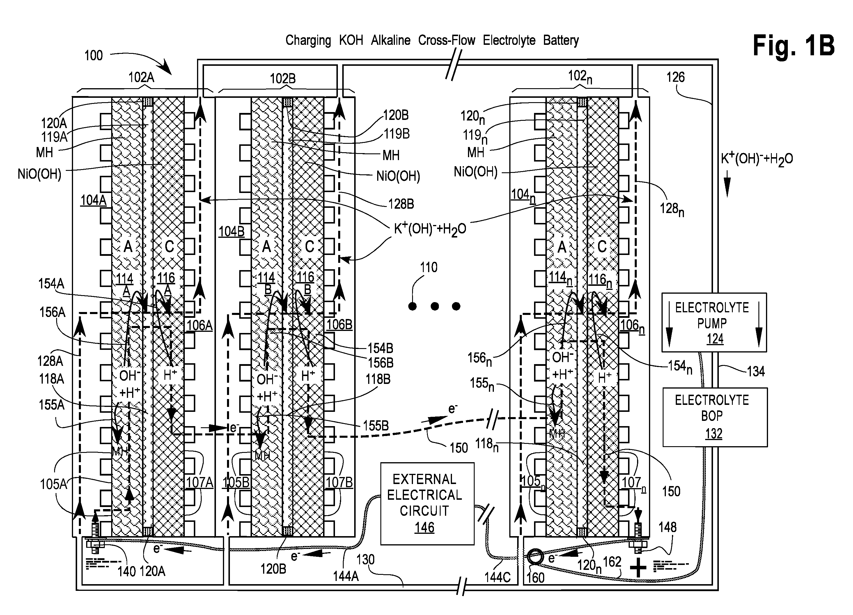
[0082]FIGS. 1A and 1B are cross-sectional views of a first embodiment of a Cross-Flow Electrochemical Battery 100 comprising a series of connected cross-flow cells 102A, 102B, . . . , 102n with separate metal anode electrolyte chambers 104A, 104B, . . . , 104n having anode contact surfaces 105A, 105B, . . . , 105n and metal cathode electrolyte chambers 106A, 106B, . . . , 106n having cathode contact surfaces 107A, 107B, . . . , 107n for each cell 102x, where 102x may be any or all of the cells 102A, 102B, . . . , 102n and n is the Roman alphabetic character of the numerical equivalent of the last cell 102n in the series (e.g., 5=E). Ellipsis 110 is a placeholder for additional cells 102C . . . 102n-1, if any.

[0083]Each of the cells 102x comprises an anode 114x—also labeled A—in electrical contact with its adjacent electrolyte chamber 104x at the anode contact surfaces 105x; a cathode 116x—also labeled C—in electrical contact with its adjacent electrolyte chamber 106x at the cathode ...

second embodiment

[0134]FIG. 2 is cross-sectional view of a second embodiment of a Cross-Flow Electrochemical Battery 200. This is a special-purpose configuration that may be preferred where energy or power density per size or weight must be maximized or the CFEB 200 need only be charged and discharged once or stored in a discharged state for rapid recharge and immediate reuse. Most of manifold hardware bulk and mass found in the first embodiment has been eliminated to reduce size and weight. The second embodiment can be stored for long periods in a stable, discharged condition and quickly charged for use. The battery's limitation is that once its external electrical source or load is removed or pumping is stopped, the battery will self-discharge. In use, self-discharge is prevented by electrolyte cross-flow.

[0135]The CFEB 200 comprises a series of connected cross-flow cells 202A, 202B, 202C, . . . , 202n. Instead of separate electrolyte chambers for each cell as incorporated in CFEB 100 of the first...


PUM

PropertyMeasurementUnit
diametersaaaaaaaaaa
thicknessaaaaaaaaaa
thicknessaaaaaaaaaa

Abstract

A cross-flow electrochemical cell for producing electricity is disclosed that incorporates means for cross-flow pumping of electrolyte through both anode and cathode electrodes in the same direction to achieve markedly higher discharging and charging currents. Cross-flow pumping enabling use of thick mesh electrodes comprising scaffolds impregnated with high-surface-area metal nanoparticles and having high porosity are also taught.

Description

CROSS-REFERENCE TO RELATED APPLICATIONS[0001]This patent application claims the benefit of U.S. Provisional Patent Application No. 61 / 388,359 filed 30 Sep. 2010, and of International Patent Application No. PCT / US10 / 39885 filed 25 Jun. 2010, which is a continuation-in-part of U.S. patent application Ser. Nos. 12 / 800,658; 12 / 800,710; 12 / 800,657; 12 / 800,672 (U.S. Pat. No. 7,972,747 of 5 Jul. 2011); and 12 / 800,709 (U.S. Pat. No. 7,964,301 of 21 Jun. 2011)—all filed on 20 May 2010. All of these applications claim priority from U.S. Provisional Patent Application 61 / 220,583 filed 26 Jun. 2009, are hereby incorporated herein by reference in their entirety and have been assigned to the assignee of this application.STATEMENT REGARDING FEDERALLY SPONSORED RESEARCH OR DEVELOPMENT[0002]Not ApplicableTHE NAMES OF PARTIES TO A JOINT RESEARCH AGREEMENT[0003]Not ApplicableINCORPORATION-BY-REFERENCE OF MATERIAL SUBMITTED ON A COMPACT DISK[0004]Not ApplicableBACKGROUND OF INVENTION[0005]1. Field of t...

Claims


Application Information

Patent Timeline
Patent Type & Authority Applications(United States)
IPC IPC(8): H01M10/42H01M10/48H01M2/40H01M50/77
CPCY02E60/50H01M8/08H01M8/22H01M8/225H01M4/8626H01M4/8673H01M8/04798H01M4/9041H01M8/04186H01M8/04276H01M8/0438H01M8/04388H01M8/04395H01M4/9016
Inventor FISCHEL, HALBERT
Owner GLOBAL ENERGY SCI CALIFORNIA
Why Eureka
Try Eureka