
Compositions and method for removing photoresist and/or resist residue at pressures ranging from ambient to supercritical

a technology of photoresist and supercritical, applied in the direction of photomechanical equipment, instruments, liquid cleaning, etc., can solve the problems of large geometries becoming "killer" defects of devices with sub-micron critical dimensions, surface states and charges, and the residue of plasma etching process, etc., to accelerate photoresist stripping, accelerate photoresist stripping, and increase the reaction kinetics and mass transport of reactant and product species

Inactive Publication Date: 2004-03-18
SCP GLOBAL TECH INC
View PDF52 Cites 100 Cited by
  • Summary
  • Abstract
  • Description
  • Claims
  • Application Information

AI Technical Summary

Benefits of technology

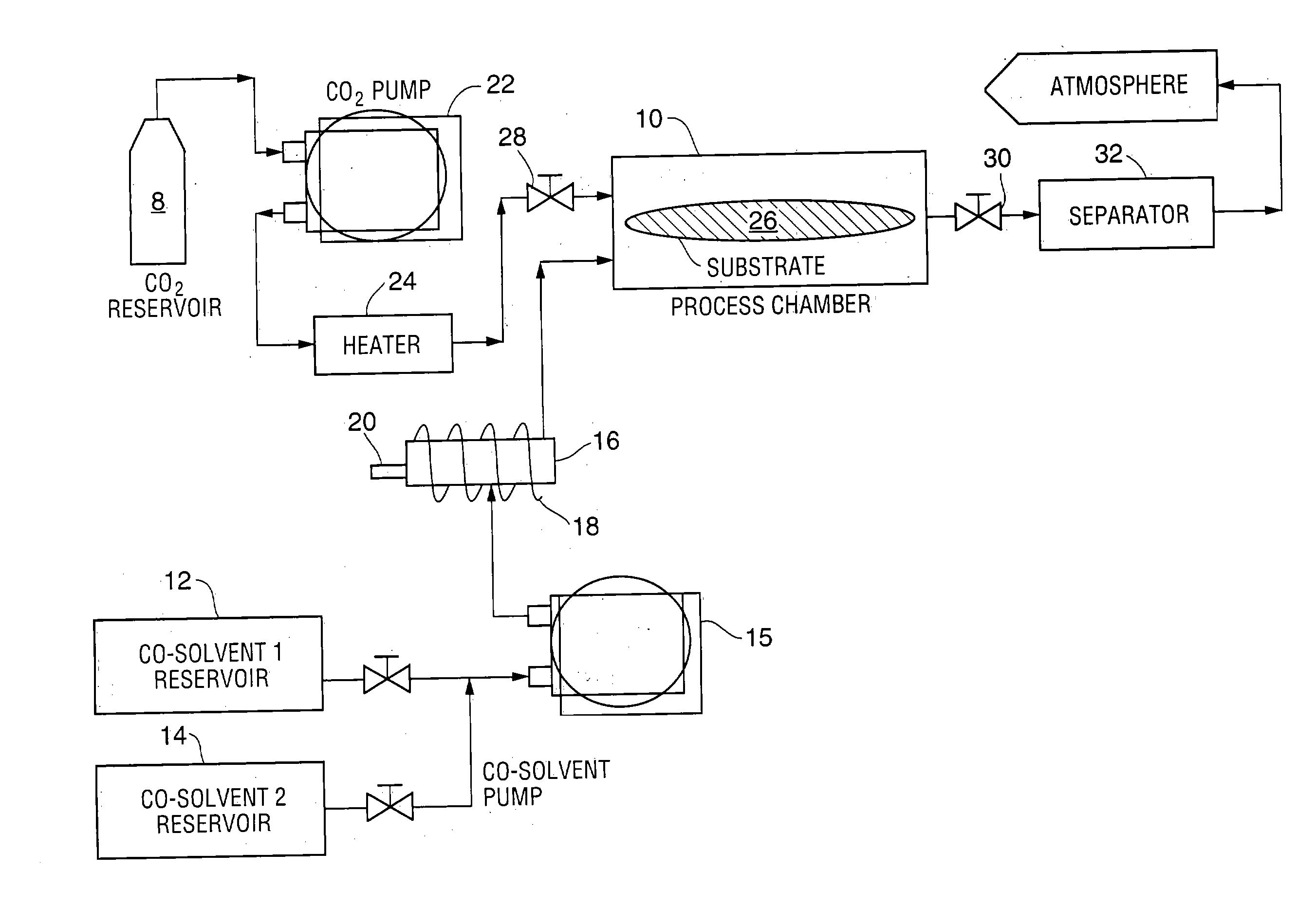
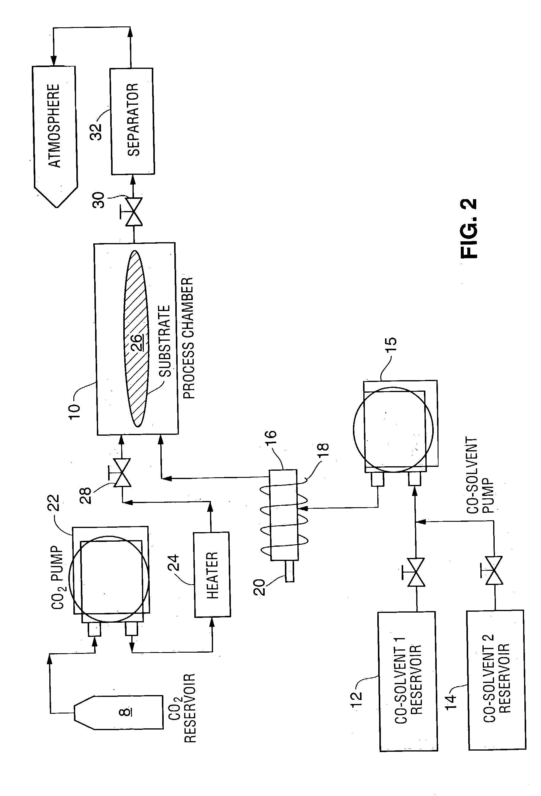
[0027] In the disclosed methods and compositions for resist stripping and / or resist residue removal cleaning is accomplished using a co-solvent mixture. This co-solvent mixture can be tailored to selectively attack only the resist and / or resist residue without damaging the sub-micron semiconductor device structures. The role of scCO.sub.2 is to act as a pressurizing medium so that the surface tension of the co-solvent mixture is decreased such that it can easily penetrate (and be removed from) the high aspect vias in sub-micron semiconductor device structures. This leads to complete wetting of all surfaces to accomplish complete, uniform cleaning. The pressure of the scCO.sub.2 system increases the reaction kinetics of the co-solvent mixture attack, thereby accomplishing cleaning in a shorter time.
[0070] The near zero surface tension of the supercritical fluid and reduced surface tension of the co-solvent mix allow penetration of the supercritical fluid and / or the co-solvent into high aspect ratio structures that are commonly found in integrated circuits. Without complete co-solvent penetration, residue removal from the bottom and the sidewalls of high aspect ratio structures is not possible. This process has been shown to work for removing blanket photoresist films that may have been hardbaked (e.g. to drive off the solvent and improve the adhesion of the photoresist material to the substrate surface and / or the barrier layer). Some of the hardbaked photoresist may be further cross-linked under high intensity UV lamps to achieve 100% cross-linking of the photoresist. A 100% cross-linked photoresist structure improves the intended performance of the photoresist but makes the photoresist very difficult to remove.

Problems solved by technology

Contamination that may not have affected the electrical performance and reliability of devices with large geometries may become a "killer" defect for devices with sub-micron critical dimensions.
Undesired resist and / or resist residue can have deleterious effects on subsequent processes such as metallization, or cause undesirable surface states and charges.
While the high temperature in the plasma process chamber oxidizes the photoresist and removes it, the plasma etch process leaves post-ash residues--undesirable byproducts from the reaction of the plasma gases, reactant species and the photoresist.
Moreover, the plasma etch procedure for resist removal is less desirable for substrates having low dielectric constant (or "low-k") films as insulating layers.
Despite a long history of wet stripping photoresists and resist residues, the semiconductor industry is faced with a challenging problem in removing photoresist and / or resist residues.
These resists have proved to be more difficult to remove than the resists they replaced.
The result is that the high vacuum and temperature conditions of the etcher produce extensively cross-linked photoresist and / or resist residue, which are not satisfactorily removed by commercial strippers.
In addition, the formulations of these strippers contain toxic solvents and solvent combinations.
While these solvents and solvent combinations were once accepted as useful, they have come under increasing public scrutiny and governmental regulation for the health and environmental risks they pose.
Nevertheless, the industry lacks a first-rate method of removing photoresist and / or resist residue from high aspect ratio openings such as submicron grooves, narrow crevices etc. without damaging the structure being produced.
Prior attempts to use scCO2 in photoresist removal processes have achieved limited success.
The resulting processes have been commercially undesirable for various reasons.
For example, the existing processes require unduly long processing times for complete photoresist and residue removal, and / or use excessive amounts of process fluids, and / or require unacceptable quantities of toxic substances, and / or negatively impact device performance, and / or fail to completely remove photoresist and resist residues.

Method used


Image

  • Compositions and method for removing photoresist and/or resist residue at pressures ranging from ambient to supercritical
  • Compositions and method for removing photoresist and/or resist residue at pressures ranging from ambient to supercritical
  • Compositions and method for removing photoresist and/or resist residue at pressures ranging from ambient to supercritical

Examples


example 1

[0074] In a first example, a substrate having a hard baked I-line photoresist that was DUV stabilized using UV lamps to achieve 100% cross-linking was placed in the process chamber. A co-solvent 1 composition of 40% (by weight) 1,2-Butylene Carbonate, 30% Dimethyl Sulfoxide, and 30% of 30% hydrogen peroxide was mixed at a temperature of 55.degree. C.

[0075] The 1,2-Butylene Carbonate was selected for its high solvency and the fact that it makes a single-phase solution with hydrogen peroxide. Ethylene or Propylene Carbonate or blends of Ethylene and Propylene Carbonate may be substituted for the 1,2-Butylene Carbonate (and vice versa) in this and the following examples. The hydrogen peroxide was selected for its ability to attack the cross-linked bonds of the photoresist, and the dimethyl sulfoxide was selected for its ability to carry out photoresist stripping. This mixture was made to flow into the process chamber and onto the substrate at a rate of 8 g / min for approximately 90 seco...

example 2

[0078] In the second example, the co-solvent mix was unchanged but was introduced into the process chamber in higher amounts at the start of the run. The complete process was run without any static dwell in the process chamber. A substrate having a hard baked I-line photoresist that was DUV stabilized using UV lamps to achieve 100% cross-linking was placed in the process chamber. A co-solvent 1 composition of 40% (by weight) 1,2-Butylene Carbonate, 30% Dimethyl Sulfoxide, and 30% of 30% hydrogen peroxide was mixed at a temperature of 50.degree. C. This mixture was made to flow into the process chamber and onto the substrate at a rate of 20 g / min for approximately 30 seconds. Supercritical carbon dioxide was caused to flow into the chamber with the co-solvent 1 at a flow rate of 60 g / min to have a total fluid flow rate into the process chamber at 80 g / min. Subsequently the co-solvent 1 flow rate was decreased to 2.4 g / min and the supercritical carbon dioxide flow rate increased to 77...

example 3

[0081] The third example is similar to Example 2, but differs in that a different co-solvent 1 composition was used. A substrate having a hard baked I-line photoresist that was DUV stabilized using UV lamps to achieve 100% cross-linking was placed in the process chamber. A co-solvent 1 composition of 40% (by weight) 1,2-Butylene Carbonate, 40% Benzyl Alcohol, and 20% of 30% hydrogen peroxide was mixed at a temperature of 50.degree. C. This mixture was made to flow into the process chamber and onto the substrate at a rate of 20 g / min for approximately 45 seconds. Supercritical carbon dioxide was caused to flow into the chamber with the co-solvent 1 at a flow rate of 60 g / min to have a total fluid flow rate into the process chamber at 80 g / min. Subsequently the co-solvent 1 flow rate was decreased to 2.4 g / min and the supercritical carbon dioxide flow rate increased to 77.6 g / min. for the next 3 minutes and 15 seconds. The operating temperature and pressure within the chamber were 110...


PUM

PropertyMeasurementUnit
critical pressureaaaaaaaaaa
critical temperatureaaaaaaaaaa
temperaturesaaaaaaaaaa

Abstract

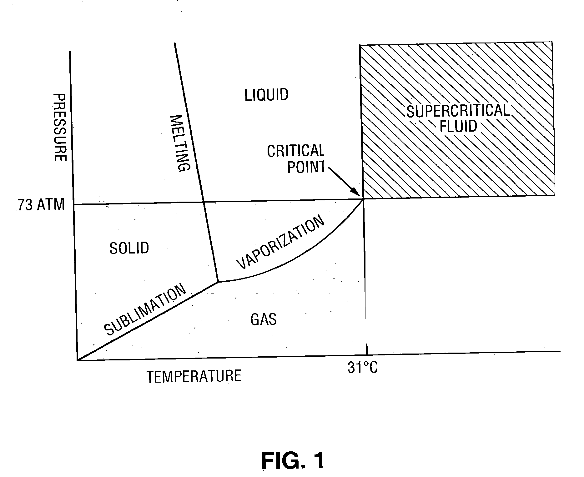
A method of enhancing removal of photoresist and / or resist residue from a substrate includes exposing the substrate to an environmentally friendly, non-hazardous co-solvent mixture comprising a carbonate, an oxidizer and an accelerator. The stripping process may be performed under ambient conditions, or in the presence of a supercritical fluid such as supercritical carbon dioxide with the supercritical cleaning step itself being a desirable "green" process. In one embodiment, the co-solvent mixture includes propylene carbonate, benzyl alcohol, hydrogen peroxide and an accelerator such as formic acid. If desired, supercritical carbon dioxide in combination with a second co-solvent mixture may be subsequently applied to the substrate to rinse and dry the substrate. In one embodiment, the second co-solvent mixture includes a lower alkyl alcohol such as isopropyl alcohol.

Description

PRIORITY[0001] This application is a continuation-in-part of U.S. application Ser. No. 10 / 197,384, filed Jul. 17, 2002, which is incorporated herein by reference.[0002] The present invention relates to compositions and methods for removing photoresist and / or resist residue from a semiconductor substrate at pressures ranging from ambient to supercritical.BACKGROUND OF THE DISCLOSURE[0003] The semiconductor industry continues to make chips that are faster in performance and cheaper in cost. This has been achieved by making the devices smaller, more complex and by creating multi-level metallization structures. To keep these miniaturized circuits operational, stringent cleanliness requirements are vital. Contamination that may not have affected the electrical performance and reliability of devices with large geometries may become a "killer" defect for devices with sub-micron critical dimensions. It is thus highly desirable to minimize the amount of contamination present on the substrate...

Claims


Application Information

Patent Timeline
Patent Type & Authority Applications(United States)
IPC IPC(8): G03F7/42
CPCG03F7/422G03F7/423H01L21/02101G03F7/426G03F7/425
Inventor SEHGAL, AKSHEY
Owner SCP GLOBAL TECH INC
Learn More