Plasma process for surface treatment of workpieces

a workpiece and surface treatment technology, applied in chemical vapor deposition coatings, electrical devices, coatings, etc., can solve the problems of affecting the surface treatment effect, and requiring a longer period of time for the evacuation of the reactor by pumping, so as to achieve uniform surface treatment

Inactive Publication Date: 2007-12-27
STRAEMKE SIEGFRIED +1
View PDF6 Cites 37 Cited by
  • Summary
  • Abstract
  • Description
  • Claims
  • Application Information

AI Technical Summary

Benefits of technology

[0007] It is an object of the present invention to provide a

Problems solved by technology

The pressure changes make discharges more difficult.
Evacuation of the reactor by pumping re

Method used


Image

  • Plasma process for surface treatment of workpieces
  • Plasma process for surface treatment of workpieces
  • Plasma process for surface treatment of workpieces

Examples


Embodiment Construction

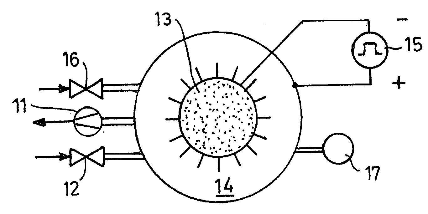
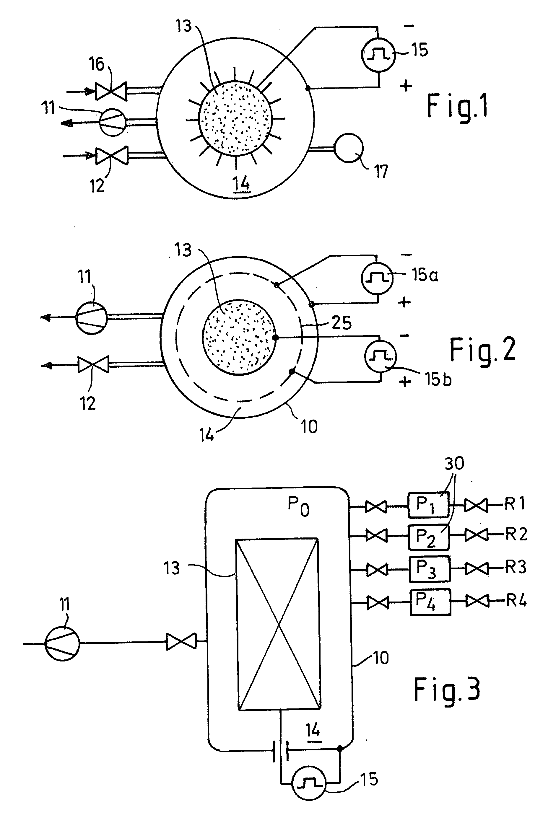
[0021]FIG. 1 shows a pressure-tight reactor 10 in which a vacuum pump 11 can generate a vacuum. A process gas can be introduced into the reactor 10 via a valve 12 for the purpose of creating an atmosphere suitable for the plasma to be produced and for causing a mass transport, with the plasma, to a workpiece.

[0022] The reactor 10 includes a workpiece 13 arranged in a reactor space 14 in an isolated manner or at a defined potential and in spaced relationship to the reactor wall. The workpiece 13 is made of a conductive material, in particular metal. The wall of the reactor 10 is also made of metal. The wall of the reactor 10 and the workpiece 13 are connected to a voltage source 15. The positive pole of the voltage source 15 is connected to the wall of the reactor 10 which defines a counter electrode for the workpiece 13. The negative pole of the voltage source is connected to the workpiece 13. The voltage source 15 is a pulsed voltage source, for example, as described in DE 33 22 3...


PUM

PropertyMeasurementUnit
Dynamic viscosityaaaaaaaaaa
Forceaaaaaaaaaa
Partial pressureaaaaaaaaaa

Abstract

In a pressure-tight reactor (10) a partial vacuum is generated in which a workpiece (13) is subjected to a plasma treatment. The pressure in a space (14) of said reactor (10) is periodically or aperiodically changed. Thus the surface layer of the workpiece (13) is rendered more uniform.

Description

RELATED FOREIGN APPLICATION [0001] The present application claims the priority of German Patent Application No. 10 2006 023 018.3 the disclosure of which is herewith incorporated herein by reference. BACKGROUND OF THE INVENTION [0002] 1. Field of the Invention [0003] The present invention relates to a plasma process for surface treatment of workpieces, wherein in a reactor a plasma discharge between an electrode and the workpiece takes place under partial vacuum conditions. [0004] 2. Description of Related Art [0005] It is known to perform a workpiece surface treatment in plasma by diffusion and / or coating. These processes include, for example, plasma nitration, plasma carbonization, plasma boration, plasma oxidation and coating with substances for improving the surface qualities, such as wetting, heat conduction, corrosion, wear, friction behavior etc. The surface treatment can be performed by PVD (physical vapor deposition), PACVD (plasma-activated chemical vapor deposition) or si...

Claims


Application Information

Patent Timeline
IPC IPC(8): H05H1/24
CPCC23C8/36H01J37/32449H01J37/3244C23C16/45557
Inventor STRAEMKE, SIEGFRIEDSTRAEMKE, MARK
Owner STRAEMKE SIEGFRIED
Why Eureka
Try Eureka