Dcdc converter, semiconductor device, and power generation device

a power generation device and converter technology, applied in the direction of electric variable regulation, process and machine control, instruments, etc., can solve the problems of low power input to a dcdc converter, long continuous operating time of a portable electronic device including the semiconductor device, and low power consumption of the semiconductor device, so as to reduce the power loss inside the dcdc converter, suppress the reduction of power conversion efficiency, and reduce the power consumption of the control circuit

Active Publication Date: 2012-04-12
SEMICON ENERGY LAB CO LTD
View PDF5 Cites 23 Cited by
  • Summary
  • Abstract
  • Description
  • Claims
  • Application Information

AI Technical Summary

Benefits of technology

[0018]In one embodiment of the present invention, generation of a control signal in a control circuit is stopped when input power is small, so that power consumption of the control circuit can be reduced. Thus, power loss inside the DCDC converter can be reduced even when input power is small, so that a reduction in power conversion efficiency can be suppressed. In addition, in one embodiment of the present invention, a reduction in power consumption of a semiconductor device including the DCDC converter can be achieved. In addition, in one embodiment of the present invention, improvement of power conversion efficiency of a power generation device including the DCDC converter can be achieved.

Problems solved by technology

Improvement of power conversion efficiency of the DCDC converter leads to lower power consumption of a semiconductor device and a long continuous operating time of a portable electronic device including the semiconductor device.
Thus, in the case where the amount of obtained electric power is small in a power generation portion of a solar battery, for example, the amount of power inputted to a DCDC converter is also small.
Further, in a switching-type DCDC converter, in the case where the amount of input power is large, power conversion efficiency is kept high; however, in the case where the amount of input power is small, power conversion efficiency is low.
Accordingly, in the case where the amount of power obtained in a power generation portion is small, the amount of power supplied from a DCDC converter to a secondary battery or a load is also small.
As a result, a problem such that charge in a power storage portion is not performed or operation in a load is not normally performed is often caused.

Method used


Image

  • Dcdc converter, semiconductor device, and power generation device
  • Dcdc converter, semiconductor device, and power generation device
  • Dcdc converter, semiconductor device, and power generation device

Examples


embodiment 1

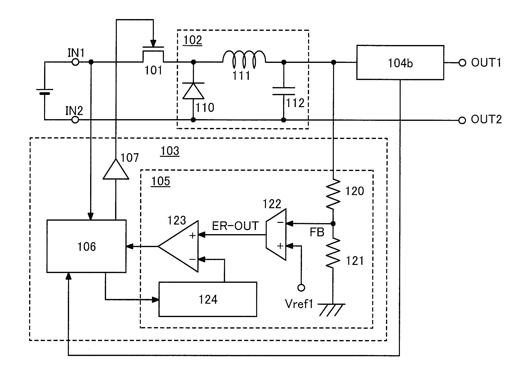
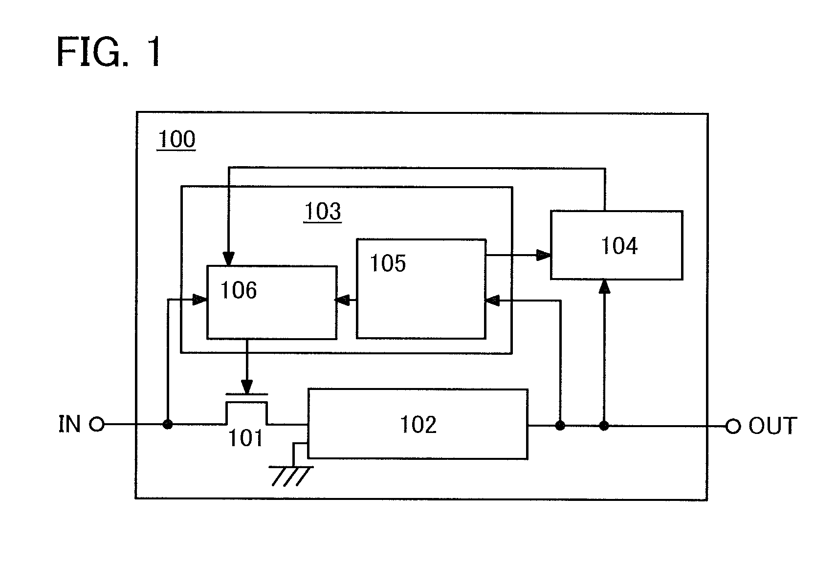
[0033]FIG. 1 shows an example of a structure of a DCDC converter according to one embodiment of the present invention. A DCDC converter 100 shown in FIG. 1 includes a transistor 101 serving as a switching element, a voltage conversion portion 102, a control circuit 103, and a detection circuit 104.

[0034]The transistor 101 controls supply of voltage supplied to an input terminal IN (input voltage) to the voltage conversion portion 102. Specifically, when the transistor 101 is turned on, the input voltage is supplied to the voltage conversion portion 102, and when the transistor 101 is turned off, the supply is stopped. In addition, when the transistor 101 is turned off, fixed voltage such as ground potential is supplied to the voltage conversion portion 102. Thus, in response to switching of the transistor 101, a signal with a pulse voltage waveform in which the input voltage and the fixed voltage appear alternately is supplied to the voltage conversion portion 102.

[0035]The voltage ...

embodiment 2

[0089]In this embodiment, an example of a lighting device which is one of semiconductor devices according to one embodiment of the present invention will be described. FIG. 9 illustrates an example of a structure of a lighting device.

[0090]The lighting device in FIG. 9 includes an AC power source 301, a switch 302, a rectification circuit 303, the DCDC converter 100, and a light-emitting element 304. The rectification circuit 303 and the DCDC converter 100 form a power supply circuit.

[0091]The DCDC converter 100 in FIG. 9 has the same structure as that of the DCDC converter 100 in FIG. 3 or FIG. 7. Specifically, in the lighting device in FIG. 9, AC voltage from the AC power source 301 is supplied to the rectification circuit 303 through the switch 302 and rectified. DC voltage obtained by the rectification is input to the DCDC converter 100 and is output after the level is adjusted. Description in Embodiment 1 can be referred to for specific operation of the DCDC converter 100.

[0092...

embodiment 3

[0097]In this embodiment, one embodiment of a solar power generation device which is one of power generation devices according to one embodiment of the present invention will be described. FIG. 10 shows an example of a structure of a solar power generation device.

[0098]The solar cell in FIG. 10 includes a photodiode 350 serving as a solar battery, a switch 351, a capacitor 352, the DCDC converter 100, a pulse width modulation circuit 353, an inverter 354, and a band pass filter 355.

[0099]The DCDC converter 100 in FIG. 10 has the same structure as that of the DCDC converter in FIG. 3 or FIG. 7. Specifically, in the solar power generation device in FIG. 10, voltage is generated when light is delivered to the photodiode 350. The voltage smoothed by the capacitor 352 is input to the DCDC converter 100 through the switch 351. Note that with the capacitor 352, the pulsed current generated by switching of the switch 351 can be prevented from flowing through the photodiode 350.

[0100]Then, t...


PUM


Abstract

A DCDC converter includes a control circuit, a transistor in which switching is controlled by being supplied voltage output from the control circuit to a gate electrode of the transistor, a voltage conversion portion in which supply of input voltage is controlled by the switching of the transistor and output power commensurate with duty ratio of the switching of the transistor, and a detection circuit detecting the output power. Further, the control circuit includes a control signal generation circuit generating a control signal with a pulse voltage waveform and a selection circuit applying voltage of the control signal to the gate electrode in the case where current detected by the detection circuit is the same as or exceeds the threshold value and applying voltage for turning on the transistor to the gate electrode in the case where the current detected by the detection circuit falls below the threshold value.

Description

BACKGROUND OF THE INVENTION[0001]1. Field of the Invention[0002]The present invention relates to a DCDC converter, and a semiconductor device and a power generation device including a DCDC converter.[0003]2. Description of the Related Art[0004]A DCDC converter is a constant-voltage circuit with which a constant output voltage can be obtained regardless of the value of input voltage, and the DCDC converter is used for a power supply circuit together with a rectification circuit or the like. In particular, a power supply circuit including a switching-type DCDC converter is referred to as a switching power source or a switching regulator.[0005]The switching-type DCDC converter outputs voltage of a desired level in such a manner that voltage with a pulse waveform is formed using input voltage by a switching element and the voltage is smoothed or held in a coil, a capacitor, or the like. With a switching-type DCDC converter, internal power loss can be small theorically, whereby power con...

Claims


Application Information

Patent Timeline
Patent Type & Authority Applications(United States)
IPC IPC(8): G05F1/46H01L31/04H02M3/155
CPCH02M3/156Y02B70/10H02M1/08H02M1/0009H02M1/0032
Inventor ITO, YOSHIAKITAKAHASHI, KEI
Owner SEMICON ENERGY LAB CO LTD
Why Eureka
Try Eureka