Diagnostic method
a technology of diagnostic method and subject, applied in the direction of component separation, particle separator tube, testing metal, etc., can solve the problems of james et al 1999, too late diagnosis,
- Summary
- Abstract
- Description
- Claims
- Application Information
AI Technical Summary
Benefits of technology
Problems solved by technology
Method used
Image
Examples
examples
[0064]In the following described experimentation, the X-rays used are derived from synchrotron radiation or other monochromatic X-ray sources providing X-rays within the energy range of five to twenty-five keV.
[0065]Where the keratin-containing component studied was hair, a single hair was used. The hair was mounted on a holder under sufficient tension to maintain alignment. The holder was mounted on a motorised translation device capable of moving in 1 μm steps in the vertical and horizontal planes which enabled each sample to be precisely located in the X-ray beam. The hair fibres were mounted with the axis of the hair in the parallel plane and at a 90 degree angle of incidence to the X-ray source. The wavelength of the X-ray beam was approximately 1.1 Å and had a resolution (ΔE / E) of 1×10⁻⁴.
[0066]Each fibre was exposed to the X-ray source for a set period of time depending on the intensity of the beam. In general each sample was exposed to a total of approximately 1×10¹⁴ photons....
experiment 1
Addition of Fatty Acids to Hair
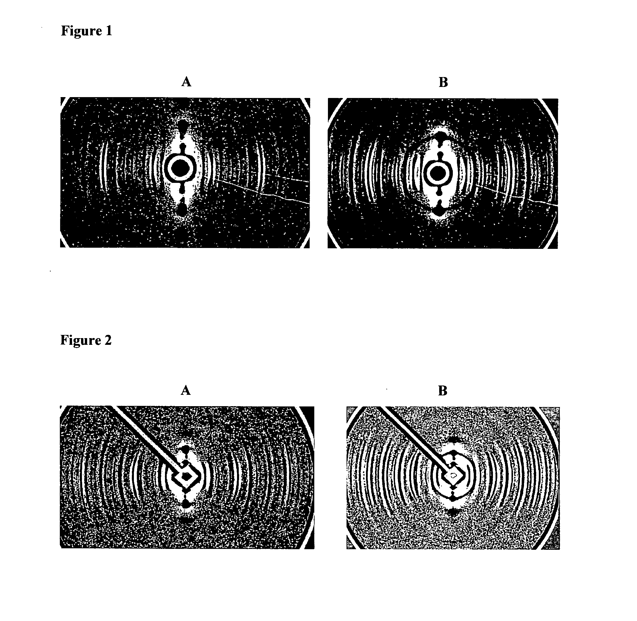
[0069]A sample of hair which did not have a ring (confirmed by X-ray diffraction) was selected. The diffraction pattern of this hair is shown in FIG. 2A.
[0070]The hair was then soaked in olive oil for 10 minutes, wiped dry and then re-exposed to X-rays. The resulting diffraction pattern is depicted in FIG. 2B wherein a clear ring is visible. The ring resulting from soaking in olive oil is very similar in appearance and d-spacing to the ring shown in FIG. 1B from a breast cancer patient.
experiment 2
Solvent Extraction of Hairs
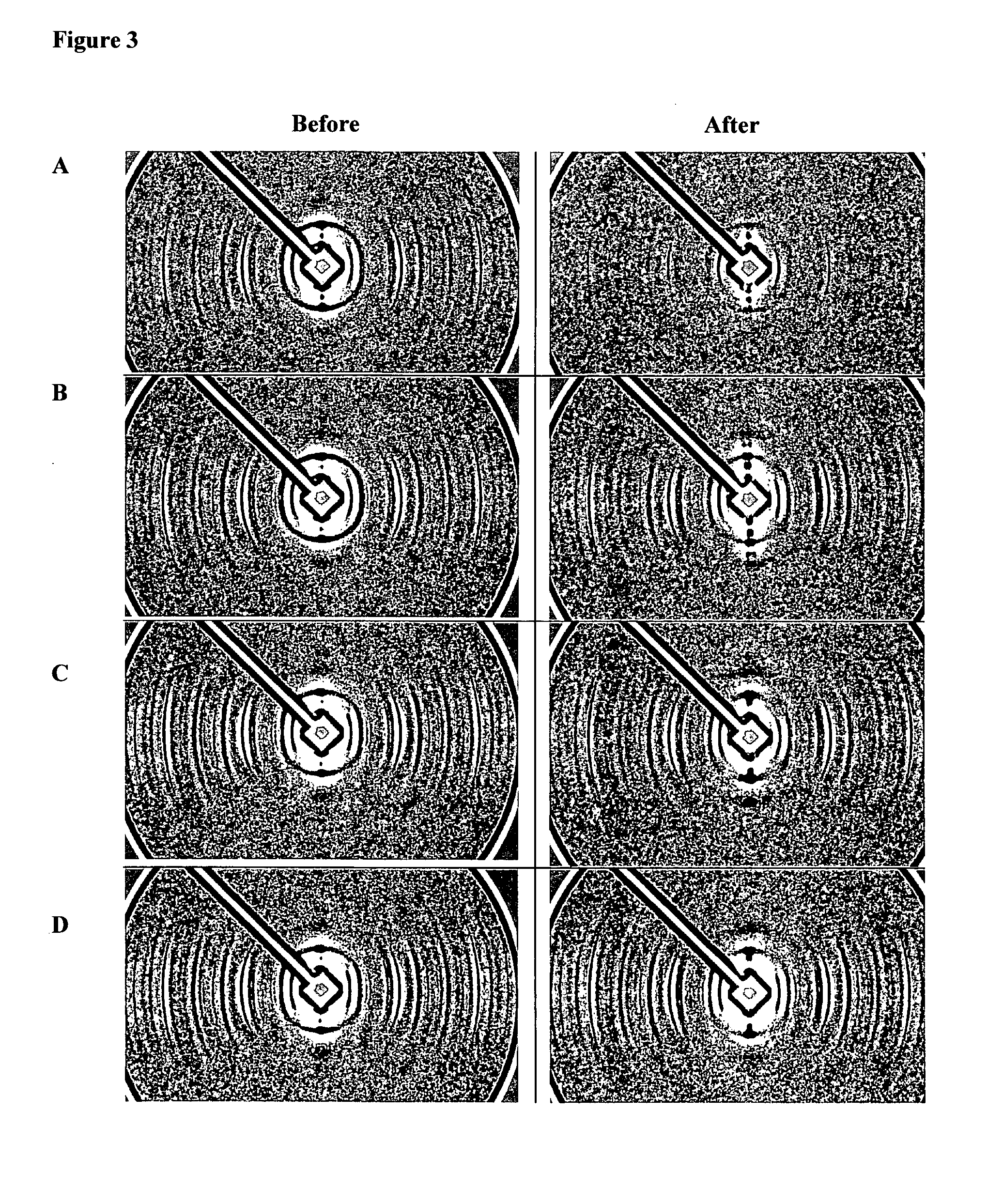
[0071]Hairs from breast cancer patients which displayed rings were run on a synchrotron SAXS beamline (Australian Synchrotron) to confirm the presence of the ring. The individual hairs were then soaked in a solvent for 2 hours, rinsed in MilliQ water, dried and then re-run very close to the same point on the hair fibre. The solvents used were:
A Isopropanol (100%);
B Chloroform (100%)
C Chloroform / methanol (1:1);
D Chloroform / methanol (1:2)
[0072]The results are shown in FIG. 3.
[0073]While all solvents reduced the intensity of the ring in most fibres, it was evident that consistently, isopropanol was the least effective and chloroform / methanol (1:2) was the most effective. This provided data to point to the species of lipid involved.
[0074]Particularly, chloroform / methanol in this ratio is used to extract neutral lipids, diacylglcerophospholipids and most sphingolipids from biological material with low lipid content.
PUM
 Abstract
Description
Claims
Application Information
 - R&D
- Intellectual Property
- Life Sciences
- Materials
- Tech Scout
- Unparalleled Data Quality
- Higher Quality Content
- 60% Fewer Hallucinations
Browse by: Latest US Patents, China's latest patents, Technical Efficacy Thesaurus, Application Domain, Technology Topic, Popular Technical Reports.
© 2025 PatSnap. All rights reserved.Legal|Privacy policy|Modern Slavery Act Transparency Statement|Sitemap|About US| Contact US: help@patsnap.com


