Radio Frequency (RF) Microwave Components and Subsystems Using Loaded Ridge Waveguide

Inactive Publication Date: 2012-04-19
UT BATTELLE LLC
View PDF4 Cites 38 Cited by
  • Summary
  • Abstract
  • Description
  • Claims
  • Application Information

AI Technical Summary

Benefits of technology

[0008]One advantage of the present invention is a reduction in component size in comparison to a similar prior art component for RF frequencies from approximately 100 to 1,000,000 MHz. Additionally, the present invention enables relatively high power capability and easier

Problems solved by technology

One disadvantage of hollow metallic waveguides is the size of the waveguide.
Thus, waveguides for radio and microwave transmissi

Method used


Image

  • Radio Frequency (RF) Microwave Components and Subsystems Using Loaded Ridge Waveguide
  • Radio Frequency (RF) Microwave Components and Subsystems Using Loaded Ridge Waveguide
  • Radio Frequency (RF) Microwave Components and Subsystems Using Loaded Ridge Waveguide

Examples


Embodiment Construction

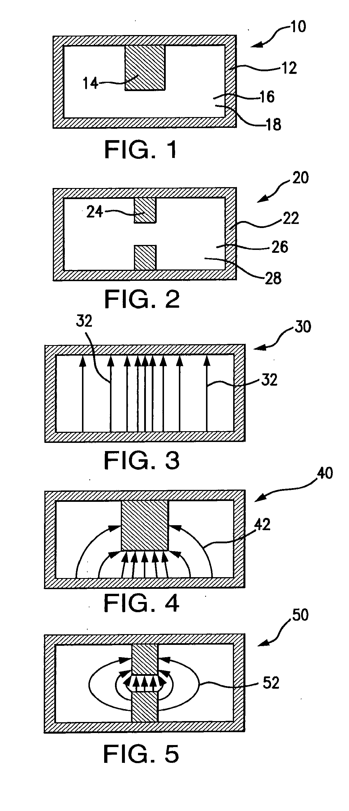
[0034]Waveguides are generally used in high power RF (radio frequency) or microwave transmission components and systems. FIG. 1 shows a cross-sectional view of a single-ridge waveguide 10 according to one embodiment of this invention. The single-ridge waveguide 10 includes a housing 12 and a ridge 14. In a preferred embodiment, the housing 12 is a metallic material for example, but not limited to, copper.

[0035]In a preferred embodiment, a volume 16 of the single-ridge waveguide 10 is filled with a non-conductive filling material 18 having a high permeability (μ, μr for relative permeability) and / or a high permittivity (∈, ∈r for relative permittivity). Filling the single-ridge waveguide 10 with the non-conductive material 18 can reduce waveguide dimensions by

∝1μr*ɛr.

The non-conductive material can comprise, for example, alumina ceramic, Teflon, or any non-conductive material with a relative permeability greater than one and / or a relative permittivity greater than one.

[0036]FIG. 2 sh...


PUM


Abstract

A waveguide having a non-conductive material with a high permeability (μ, μr for relative permeability) and/or a high permittivity (∈, ∈r for relative permittivity) positioned within a housing. When compared to a hollow waveguide, the waveguide of this invention, reduces waveguide dimensions by
1μr*ɛr.
The waveguide of this invention further includes ridges which further reduce the size and increases the usable frequency bandwidth.

Description

GOVERNMENT RIGHTS[0001]This invention was made with government support under Contract No. DE-AC05-00OR22725 awarded by the U.S. Department of Energy. The government has certain rights in the invention.FIELD OF THE INVENTION[0002]This invention is directed to a ridge waveguide having a dispersive filling material with a high permeability (μ, μr for relative permeability) and / or a high permittivity (∈, ∈r for relative permittivity) material to reduce waveguide dimensions.BACKGROUND OF THE INVENTION[0003]A waveguide is a structure that guides waves, such as electromagnetic waves or sound waves. Commonly known waveguides include hollow metal tubes which allow high frequency radio waves to “bounce” off walls of the hollow metal tubes to propagate down the waveguide. Commonly known waveguides have cross sections in rectangular, circular, or elliptical shapes. These common waveguides generally have a limited bandwidth, usually around 30% of a center of an operating frequency range.[0004]El...

Claims


Application Information

Patent Timeline
IPC IPC(8): H01P3/12
CPCH01P3/123H01P3/122
Inventor KANG, YOON W.
Owner UT BATTELLE LLC
Why Eureka
Try Eureka