Heat managing device
a technology of light-emitting diodes and heat management devices, which is applied in lighting support devices, lighting and heating apparatus, light source combinations, etc., can solve the problems of large temperature gradients in the heat sink, and achieve the effect of reducing the number of constituent parts of the device, effectively dissipating a large amount of heat, and advantageously increasing the wetting surfa
- Summary
- Abstract
- Description
- Claims
- Application Information
AI Technical Summary
Benefits of technology
Problems solved by technology
Method used
Image

Examples
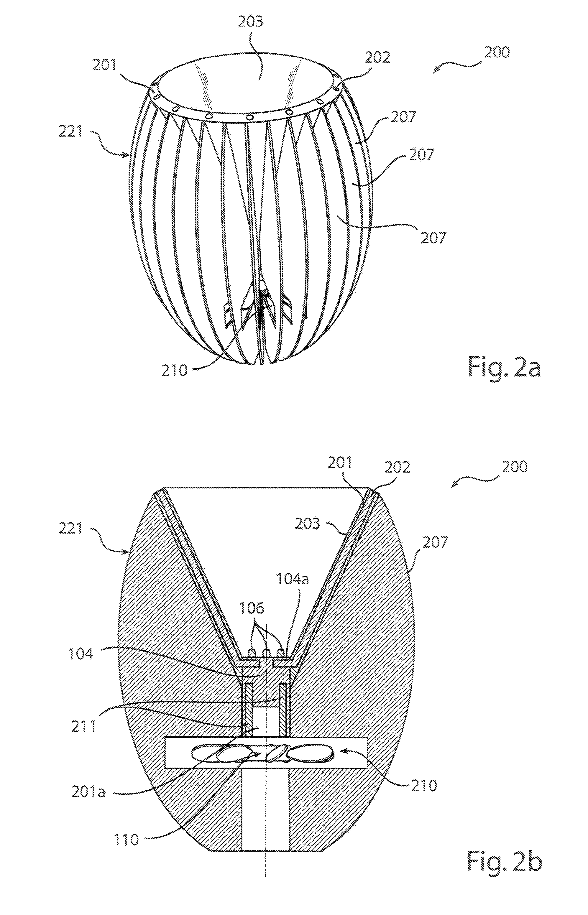
embodiment 200
[0042]Referring now to FIGS. 2a and 2b, in which an embodiment 200 in accordance with the present inventive concept is presented. The heat managing device 200 comprises a cylinder shaped heat spreader 104 arranged in thermal contact with, and at the narrow end of a conical part 201 of a heat sink 221. The conical part 201 is shaped like a truncated cone. Part of the upper surface 104a of the heat spreader 104 is encompassed by the parabolic wall formed by the conical part 201.
[0043]Further, secondary optics 203 are arranged within the parabolic wall formed by the heat sink 201. The secondary optics 203 controls the direction of light emitted from LEDs 106, which are arranged on the upper surface 104a of the heat spreader 104. The secondary optics 203 is here provided as an aluminium foil mounted to cover the inner surface of the conical part 201.
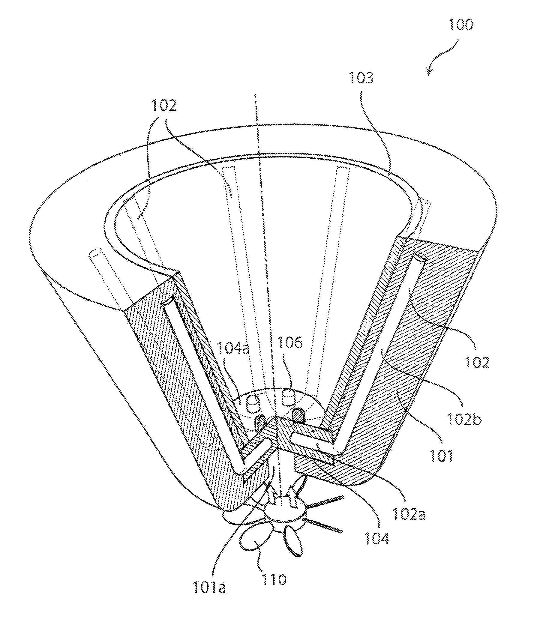
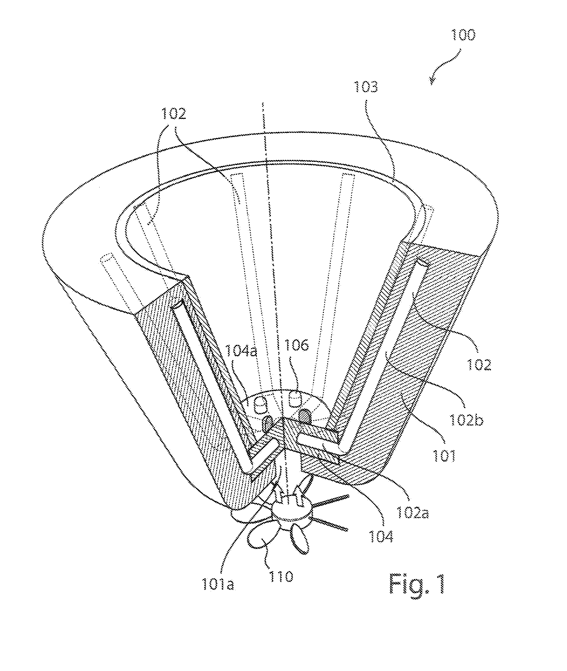
embodiment 100
[0044]Furthermore, a plurality of heat pipes 202 are partly embedded in the heat spreader 104, and arranged to extend from the heat spreader 104 into the conical part 201, and further along the extension of the wall of the conical part 201. In FIG. 2b two heat pipes 202 are visible. The heat pipes are symmetrically arranged in the heat managing device 200, and are basically arranged as in the previously described embodiment 100. However, here the heat pipes 202 extend along the wall up to the outer rim of the conical part 201. Optionally, the heat pipes may extend outside the outer rim of the conical part 201.
[0045]In alternative embodiments, the length of the heat pipes 202 are between 0.5 and 2 times the length of the secondary optics, and preferably between 0.7 and 1.3 times the length of the secondary optics. In a preferred embodiment 5-30 heat pipes are used in the first set of heat pipes, preferably between 7 and 21, most preferably 7, 9, 14 or 18. The number of heat pipes is ...
PUM
 Abstract
Description
Claims
Application Information
 - R&D
- Intellectual Property
- Life Sciences
- Materials
- Tech Scout
- Unparalleled Data Quality
- Higher Quality Content
- 60% Fewer Hallucinations
Browse by: Latest US Patents, China's latest patents, Technical Efficacy Thesaurus, Application Domain, Technology Topic, Popular Technical Reports.
© 2025 PatSnap. All rights reserved.Legal|Privacy policy|Modern Slavery Act Transparency Statement|Sitemap|About US| Contact US: help@patsnap.com