
Photovoltaic units, methods of operating photovoltaic units and controllers therefor

a photovoltaic unit and photovoltaic technology, applied in the field of photovoltaic units, can solve the problems of large drop in the output power of the pv system in question, significant drop in the efficiency of the photovoltaic system as a whole, and differences between output powers of individual solar cells in the various modules, and achieve the effect of substantial cost savings

Inactive Publication Date: 2012-04-26
NXP BV
View PDF2 Cites 127 Cited by
  • Summary
  • Abstract
  • Description
  • Claims
  • Application Information

AI Technical Summary

Benefits of technology

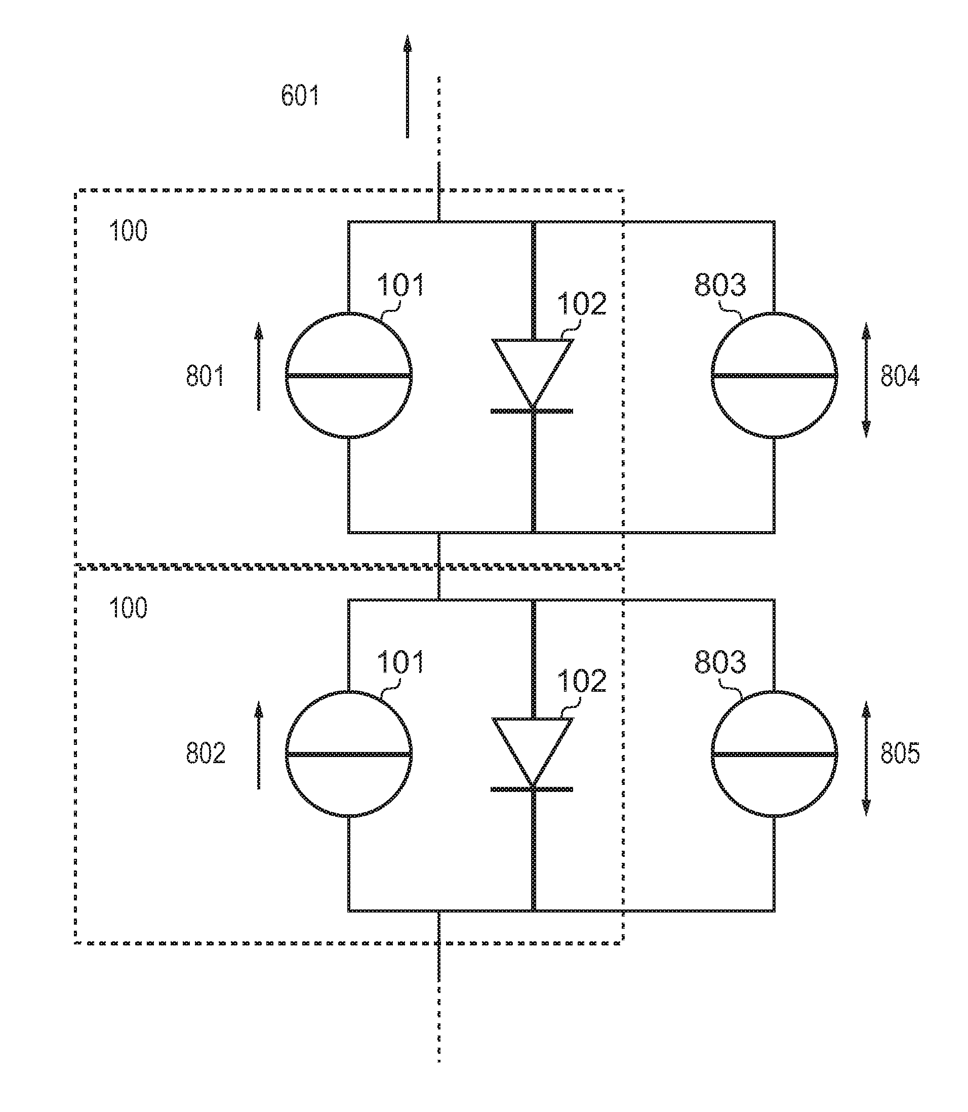
[0021]According to an aspect of the present invention, there is provided a photovoltaic unit comprising a first sub-unit and a second sub-unit series-connected with the first sub-unit, wherein the first sub-unit and second-sub-unit each comprise either a single solar cell or a series-connected plurality of solar cells, and wherein the first sub-unit further comprises a supplementary power unit connected in parallel with the respective solar cell or plurality of solar cells. The sub-unit may thereby be protected against unnecessary performance degradation due to shadowing or otherwise lower insolation. A photovoltaic unit may be without limitation one or more panels or part of a panel, or one or more modules or part of a module. Similarly, a sub-unit may be, without limitation, a panel or part of a panel, a module or part of a module, a segment of series connected cells, or even a single cell.
[0025]In embodiments, the second sub-unit further comprises a second supplementary power unit. The second sub-unit can thereby by protected against unnecessary performance degradation due to shadowing or otherwise lower insolation.
[0034]In embodiments the step of controlling the supplementary power unit to either source or sink current such that at least one of the first and second sub-units operates closer to its respective maximum power operating point than it did when then supplementary power unit is not supplying current comprises controlling the supplementary power unit to either source or sink current such that each of the first and second sub-units operates substantially at its respective maximum power operating point. The method thereby reduces or almost eliminates losses in each sub-unit due to mismatch between operating points.
[0036]In embodiments wherein the photovoltaic unit comprises a plurality of sub-units, each of which comprises at least one solar cell, and a supplementary power unit connected in parallel with the at least one solar cell, the method may further comprise controlling each supplementary power unit such that each at least one solar cell operates substantially at its maximum power operating point. Losses from multiple sub-units which are either part-shaded, or otherwise producing lower photo-generated current, may thereby be reduced or even eliminated.
[0038]Furthermore, in embodiments the total power supplied by the supplementary power units is substantially zero. Power is thereby redistributed between the subunits. In this case, the supplementary power units need be rated sufficient only to convert the maximum foreseeable difference in current between a sub-units and the average over the whole of total unit (or string). Lower (power) rated components may therefore be used resulting in potentially substantial cost savings.

Problems solved by technology

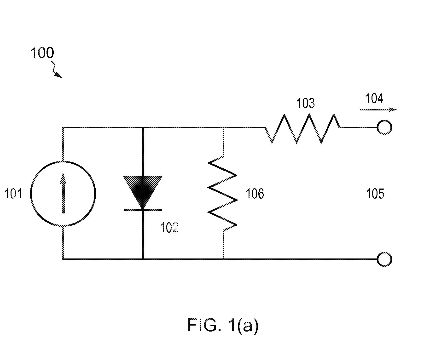
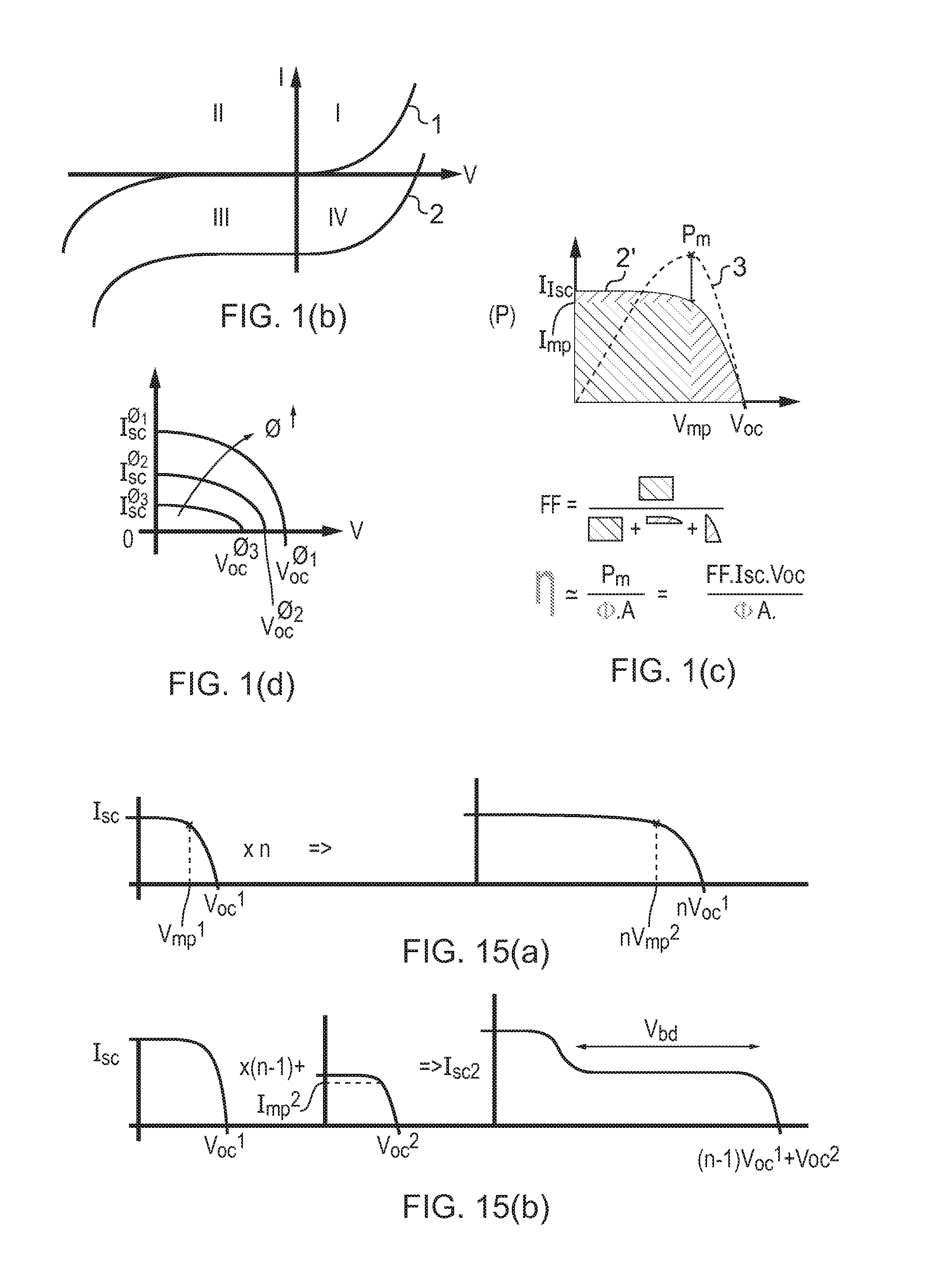
In practical cases, differences will exist between output powers of individual solar cells in the various modules, e.g. due to (part of) the modules being temporarily shaded, pollution on one or more solar cells, or even spread in solar cell behaviour—for instance due to manufacturing variations or to differences in the rate of degradation of performance of cells during aging.
As will be explained below, this will lead to a relatively large decrease in output power of the PV system in question.
This corresponds to a significant drop in efficiency for the photovoltaic system as a whole.
The bypass diode thus protects the lower-current cell from potentially damaging high reverse bias, (the so-called “hot-spot” phenomenon), and at the same time limits, but does not eliminate, the power loss in the system which results from the current mis-match.
As they have to convert all the power, all the time, they are relative large and expensive, and prone to failure.

Method used


Image

  • Photovoltaic units, methods of operating photovoltaic units and controllers therefor
  • Photovoltaic units, methods of operating photovoltaic units and controllers therefor
  • Photovoltaic units, methods of operating photovoltaic units and controllers therefor

Examples


Embodiment Construction

[0062]A conventional arrangement for a PV system is shown in FIG. 4. A solar module 400 consists of perhaps 54-72 cells 100 in series, typically arranged in a meander-type fashion with a width 402 of 9-12 cells and one bypass diode 401 per segment of 18-24 cells. The number of cells per bypass diode is typically coupled to the breakdown voltage of the solar cells used. A segment 403 comprising one series of solar cells and a bypass diode 401 is indicated as well. The 3 diodes in FIG. 4 are typically placed in a junction box 404 with a heat sink that is placed on the backside of each module.

[0063]Conventional modules exhibit a signficant decrease in output power due to sub-optimum performance of one or more PV solar cells present, e.g. due to shading, breakage, electrical disconnects, etc . In order to understand why e.g. shading of even a single or a few cells may lead to a relatively large decrease in output power of a PV system, consider a fragment of a module—also described herei...


PUM


Abstract

The present invention relates to the field of photovoltaic systems with solar cell (s) or modules having insolation differences or mismatch. Each solar module is formed by placing a large number of solar cells in series. The PV system is then formed by placing a number of solar modules in series in a string and sometimes by placing multiple strings of series-connected solar modules in parallel, depending on the desired output voltage and power range of the PV system. In practical cases, differences will exist between output powers of the solar cells in the various modules, e.g. due to (part of) the modules being temporarily shaded, pollution on one or more solar cells, or even spread in solar-cell behaviour that may become worse during aging. Due to the current-source-type behaviour of solar cells and their series connection these differences will lead to a relatively large drop in output power coming from the PV system. This invention addresses this problem by adding DC-DC converters (803) on a single or multiple solar-cell level that source or sink difference currents thereby increasing the output power of the complete PV system. In embodiments, the efficiency of photovoltaic systems with solar cell (s) or modules is improved by compensating for output-power loss caused by insolation difference and mismatch.

Description

FIELD OF THE INVENTION[0001]This invention relates to photovoltaic units. It further relates to methods for operating photovoltaic units, and to controllers configured to operate such methods.BACKGROUND OF THE INVENTION[0002]A photovoltaic cell (hereinafter also referred to as a solar cell) is a device which directly converts light such sunlight into electricity. A typical such device is formed of a p-n junction in a semiconductor material. In operation, one surface of the device is exposed to light typically through an anti-reflective coating and protective material such as glass. Contact to this surface is made by a pattern of conductive fingers typically of a metal such as aluminium. Electrical contact to the other side of the p-n junction is typically provided by a continuous metal layer.[0003]Photovoltaic (PV) systems, typically made of several hundreds of solar cells, are increasingly used to generate electrical energy from solar energy falling on solar modules. Generally, eac...

Claims


Application Information

Patent Timeline
IPC IPC(8): H02J9/00
CPCH01L31/02021H02S40/32Y02E10/566H02J7/35Y02E10/56
Inventor BERGVELD, HENDRIK JOHANNESSCHOOFS, FRANCISCUS A. C. M.HOOGZAAD, GIAN
Owner NXP BV
Learn More