System and method for uniform and localized wall thickness measurement using fiber optic sensors

a fiber optic sensor and localized wall technology, applied in the field of strain measurement, can solve the problems of insufficient insufficient exposure of fiber, and insufficient use of fiber bragg grating (fbg) sensors for uniform and localized wall thickness measurement, etc., to achieve accurate determination of wall thickness with metal loss, high signal to noise ratio, and high resolution

Active Publication Date: 2012-04-26
SCHLUMBERGER TECH CORP
View PDF9 Cites 29 Cited by
  • Summary
  • Abstract
  • Description
  • Claims
  • Application Information

AI Technical Summary

Benefits of technology

[0010]The FBGs are preferably mounted around portions of the pipe expected to have significant metal loss as well as portions of the pipe expected to have negligible metal loss. The method includes at least one of comparing relative strains at locations with negligible metal loss to those with significant metal loss to accurately determine the thickness of the wall with metal loss; compensating for temperature effects by considering relative strains at areas of the pipe with and without metal loss; and measuring axial strain on the pipe with one or more of the FBGs to correct for at least one of bending and torsion effects on hoop strain.
[0011]The use of FBG sensors has numerous advantages over wall thickness detectors employed in the prior art. The FBGs are relatively small (i.e. on the order of 1 cm long) and are capable, when employed in the system of the invention, of providing a high resolution picture of the strain experienced by a pressurized pipe wall at a number of small and discrete points. Moreover, the optical fibers that the FBGs are incorporated in are capable of providing a clean, high signal to noise ratio over long distances that is not compromised by electromagnetic interference generated by, for example, the ferric alloys used in many pressurized pipes. Finally, the exterior location of the FBGs, plus the fact that they are embedded in a composite material, advantageously protects them from corrosive fluids and mechanical shock.

Problems solved by technology

However, these techniques require exposure of the fiber to the corrosive fluids.
However, such systems do not employ Fiber Bragg Grating (FBG) sensors for uniform and localized wall thickness measurement.
Again, such systems do not employ Fiber Bragg Grating (FBG) sensors for uniform and localized wall thickness measurement.

Method used


Image

  • System and method for uniform and localized wall thickness measurement using fiber optic sensors
  • System and method for uniform and localized wall thickness measurement using fiber optic sensors
  • System and method for uniform and localized wall thickness measurement using fiber optic sensors

Examples


Embodiment Construction

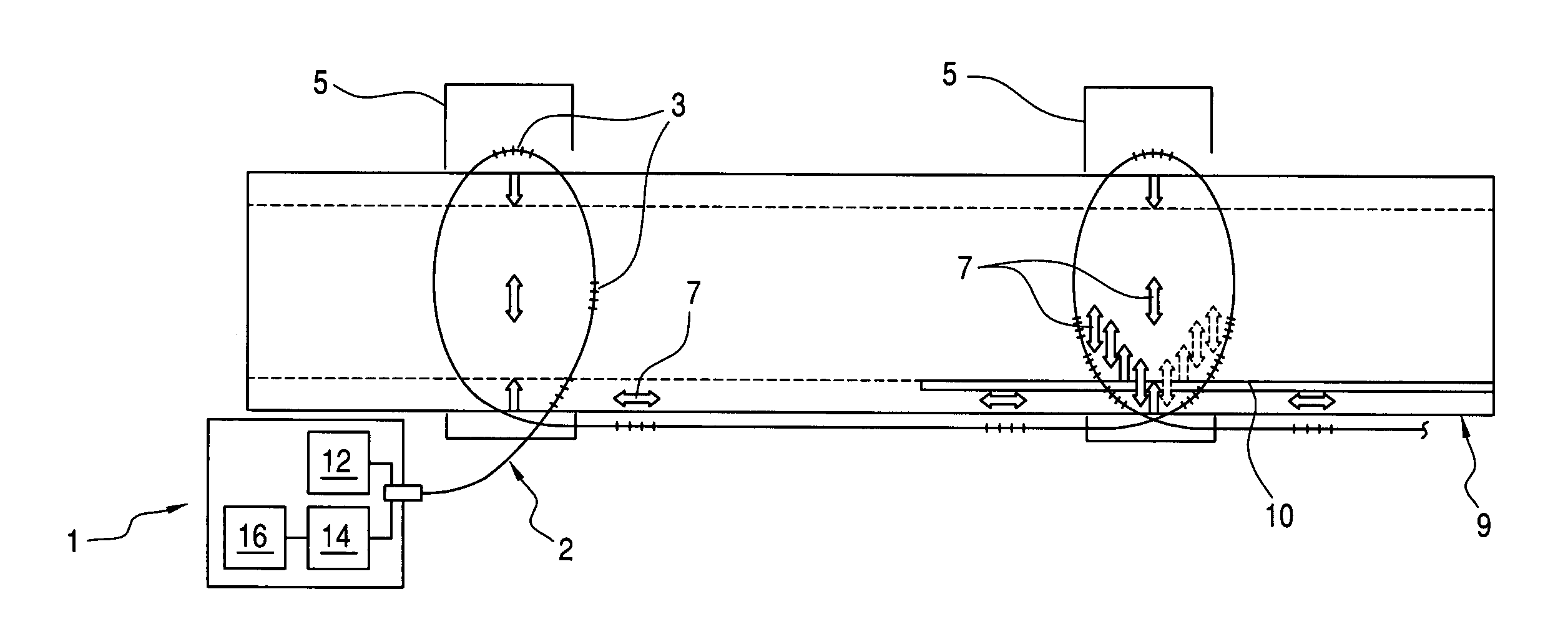
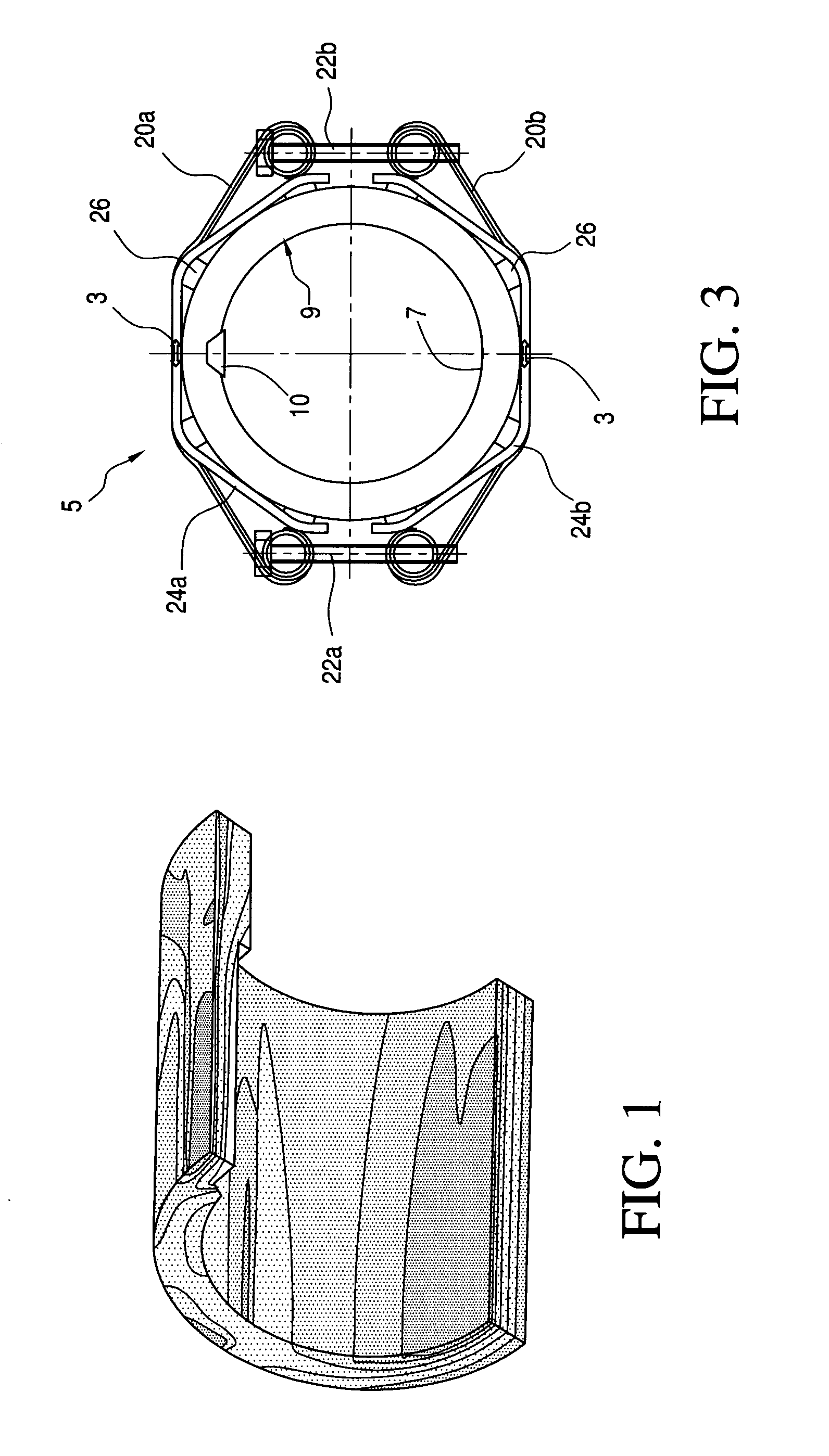
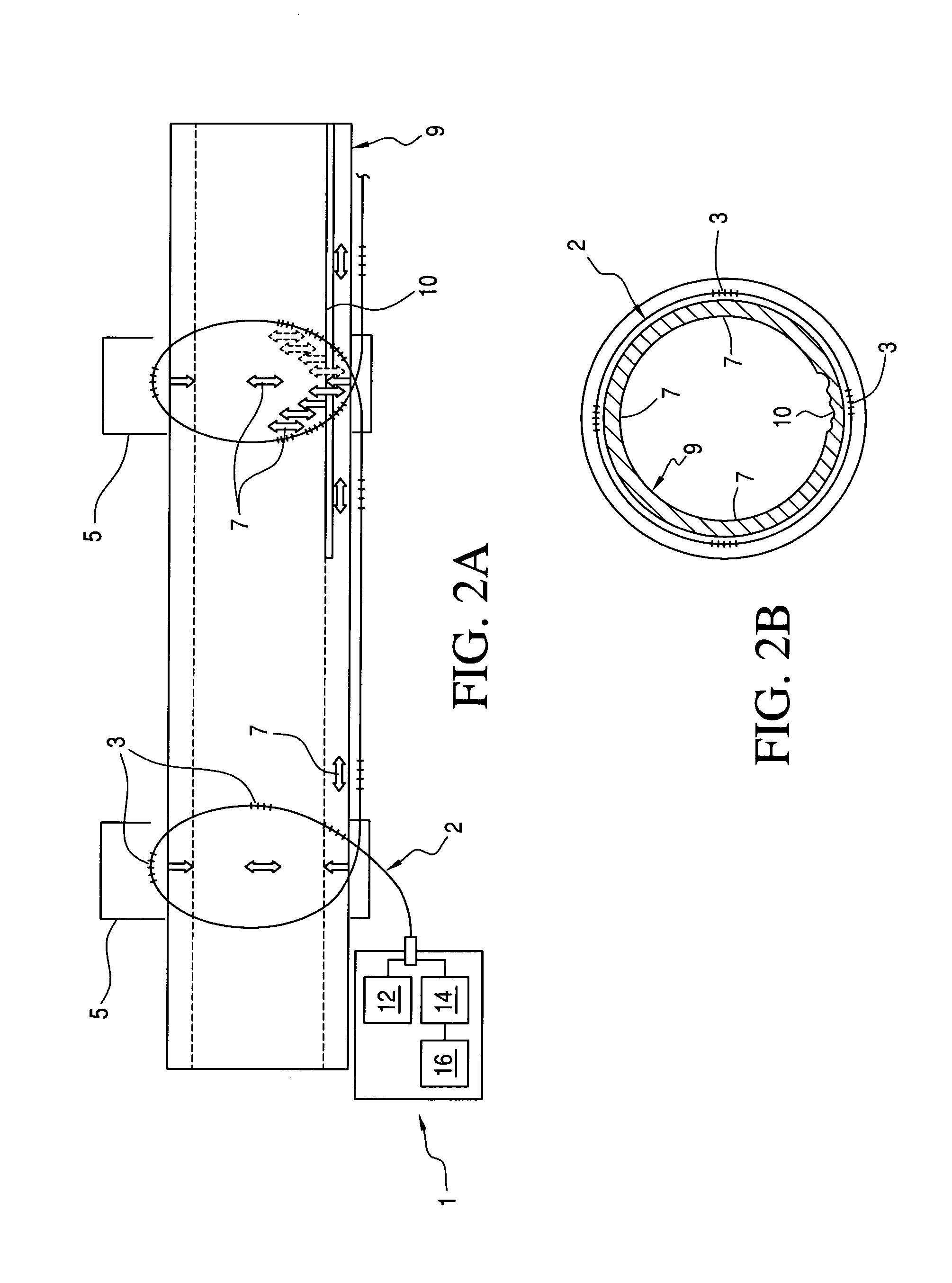
[0024]The present invention generally relates to a method and system for determining wall thickness measurements of pressurized pipes, elbows, vessels, and the like, employing fiber optics sensors, and a validation testing procedure, and working examples therefor. For example, for a pipe or vessel, the resultant strain on the structure due to internal pressure is a function of the wall thickness. Other factors including bending or twisting forces, thermal expansion, and the like, can also impact on the strain. Accordingly, in an exemplary embodiment, Fiber Bragg Gratings (FBGs) are employed to provide discrete high resolution strain measurements over the surface of pressurized pipes and vessels. The FBGs can be employed along with various correction algorithms, compensation techniques, and the like, for example, to determine wall thickness readings, and the like. In addition, the exemplary embodiments, advantageously, provide the capability to map out discrete measurements of strain...


PUM


Abstract

A system and method are provided for determining wall thickness of a structure such as a metallic pressurized pipe. The system includes an optical fiber having a plurality of Fiber Bragg Gratings (FBGs), and a mounting for securing the FBGs over discrete portions of the exterior surface of the pipe such that strain in the pressurized pipe wall is transmitted to the FBGs. The system further includes a light source and a light sensor coupled to an end of the optical fiber. The light sensor converts light reflected back from the FBGs into electrical signals that a digital processor converts into strain measurements. The FBGs are mounted around portions of the pipe expected to have significant metal loss as well as portions of the pipe expected to have negligible metal loss. The method includes at least one of comparing relative strains at locations with negligible metal loss to those with significant metal loss to accurately determine the thickness of the wall with metal loss; compensating for temperature effects by considering relative strains at areas of the pipe with and without metal loss; and measuring axial strain on the pipe with one or more of the FBGs to correct for at least one of bending and torsion effects on hoop strain.

Description

BACKGROUND[0001]1. Technical Field[0002]The present invention generally relates to methods and systems for strain measurement, and more particularly to a system and method for uniform and localized wall thickness measurement using fiber optic strain sensors.[0003]2. Discussion of Background Art[0004]Fiber optics have been employed to monitor corrosion in several different forms. A number of applications employ fiber optics to monitor the strain generated within reinforced concrete due to build up of corrosion products. Others relate to the impact of corrosion on metal coated fibers or fibers doped with compounds that fluoresce in the presence of a target chemical species. However, these techniques require exposure of the fiber to the corrosive fluids.[0005]An externally mounted fiber optics system by Fiber Optics Systems Technology, Inc. is described in “Direct Assessment of Corrosion Using Fiber Optic Sensors,” NACE, 2007, Paper no. 07385, wherein the system employs Brillouin spect...

Claims


Application Information

Patent Timeline
Patent Type & Authority Applications(United States)
IPC IPC(8): G01B11/16
CPCG01B11/06G01B11/18G01L9/0032G01D3/0365G01D5/35383G01B21/045G01D5/35316
Inventor COUPE, PETERROBERTS, DAMON RICHARDBELOV, DMITRYDEGER, EVGENIYA MYALOFUKUHARA, MASAFUMIPICO, YAMIDRAMOS, ROGERIO TADEUPEIRCE, IAN
Owner SCHLUMBERGER TECH CORP
Why Eureka
Try Eureka