Power converter with high efficiency in operation

a technology of power converter and high efficiency, which is applied in the direction of electric variable regulation, process and machine control, instruments, etc., can solve the problems of increasing switching loss, reducing the efficiency of power converter operation, and occupying passive components of the magnetic part a considerable part of the size of the power converter

Active Publication Date: 2012-04-26
DENSO CORP
View PDF10 Cites 16 Cited by
  • Summary
  • Abstract
  • Description
  • Claims
  • Application Information

AI Technical Summary

Benefits of technology

[0021]The circulating path may also have disposed therein a Zener diode whose forward direction is a direction in which electric current flows from the high-potential side to the low-potential side. This avoids the flow of current through...

Problems solved by technology

Usually, the magnetic parts that are passive components occupy a considerable part of the size of the power converter.
This requires the need for increasing the switching frequency in the power converter, but results in an increase in switching loss, which leads to a decrease in efficiency in operation of the power converter.
Specifically, the voltage developed across the switching device when turned off is restricted by a change in voltage charged in the snubber capacitor, which will lead to decrease the switching loss.
The above prior art system, however, has the problem that it is impossible to decrease the switching loss when the switching device is turned on.
Thus, when the current flowing through the inductor is small, it results in a decre...

Method used


Image

  • Power converter with high efficiency in operation
  • Power converter with high efficiency in operation
  • Power converter with high efficiency in operation

Examples


first embodiment

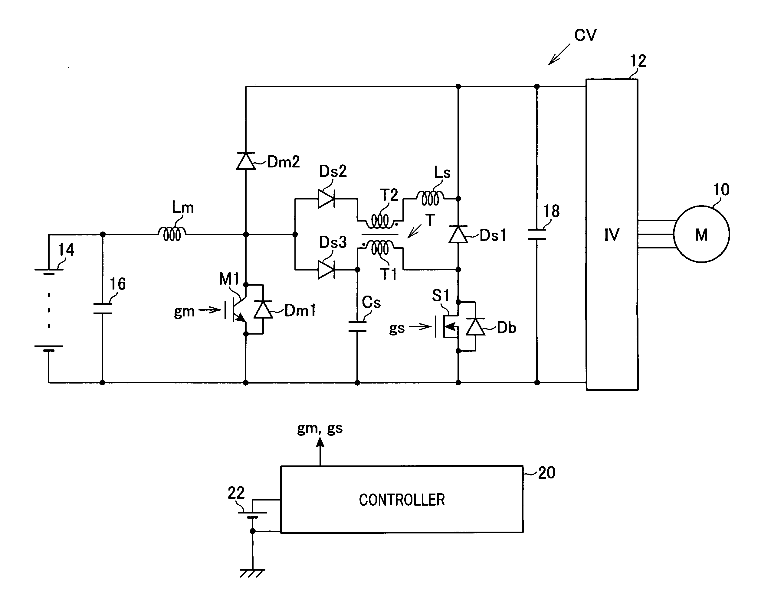
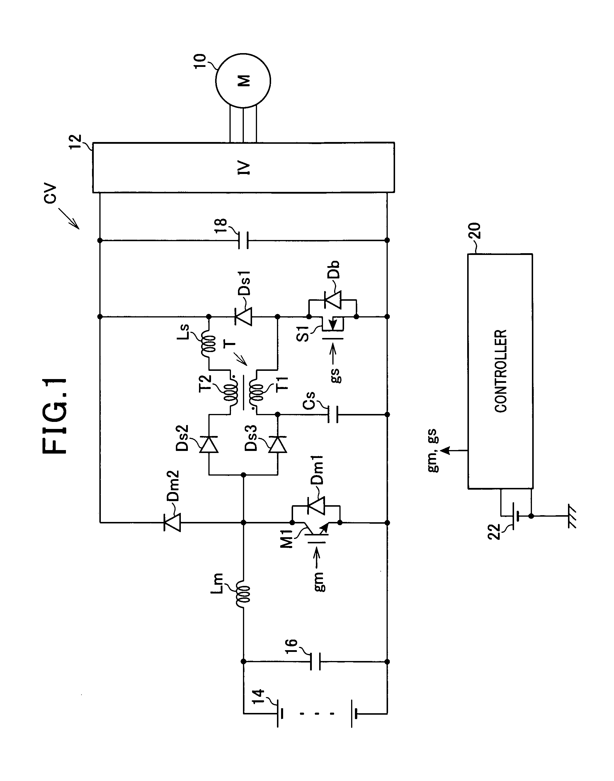
[0039]Referring to the drawings, wherein like reference numbers refer to like parts in several views, particularly to FIG. 1, there is shown a converter control system designed to control an operation of a power converter CV which is used in driving a main engine mounted in an automotive vehicle.

[0040]An electric motor-generator 10 is used as the main engine of the vehicle and has an output shaft connected mechanically to driven wheels (not shown) of the vehicle. The motor-generator 10 is joined electrically to a high-voltage battery 14 and a smoothing capacitor 16 through an inverter 12 and the converter CV. The converter CV is equipped with a sub-circuit to reduce the switching loss in a chopper circuit. Specifically, the converter CV includes a main circuit equipped with a main switch M1, a main diode Dm1 connected in inverse-parallel to the main switch M1, and a main diode Dm2 connected in series with the main switch M1 and the main diode Dm1. The converter CV also includes a m...

second embodiment

[0092]The power converter control system of the second embodiment offers an additional beneficial advantage below in addition to the advantages 1) to 7).

[0093]8) The converter CV is designed to have the capacitor which is connected in parallel to the main switch M1 and whose capacitance is variable. Specifically, when the current flowing through the main inductor Lm changes greatly, the controller 20 works to change the total capacitance of the capacitors Cs1 and Cs2, thus optimally controlling the speed at which the voltage across the ends (i.e., the collector and the emitter) of the main switch Ml increases when the main switch M1 is turned off.

[0094]The converter control system of the third embodiment will be described below with reference to FIG. 10 which is a modification of the first embodiment. The same reference numbers as employed in FIG. 1 will refer to the same parts, and explanation thereof in detail will be omitted here.

[0095]The converter CV is designed to have the sub...

fourth embodiment

[0098]The converter control system of the fourth embodiment will be described below with reference to FIG. 11. The same reference numbers as employed in FIG. 1 will refer to the same parts, and explanation thereof in detail will be omitted here.

[0099]The converter CV is designed to have two sub-circuits installed in a bi-directional step-up chopper circuit. The bi-directional step-up chopper circuit is made up of two structures one of which is the same as that of the step-up chopper circuit of the first embodiment and other of which is the same as that of the step-down chopper circuit of the third embodiment. The sub-circuits are provided one for each of the main switches M1 and M2.

[0100]When it is required to step-up the current to be outputted from the high-voltage battery 14 to the capacitor 18, a lower circuitry (i.e., a lower one of the sub-circuits) of the bi-directional step-up circuit, as viewed in the drawing, which is equipped with the capacitor Cs connected in parallel to...


PUM


Abstract

A power converter includes a main switch to which a capacitor is connected through a sub-diode. A primary coil of a transformer and a sub-switch are joined parallel to the capacitor. A main diode is coupled in series with the main switch. A sub-diode and a secondary coil of the transformer are connected parallel to the main diode. The rate of a rise in voltage across the main switch when turned off is suppressed by the rate of charging of the capacitor. Subsequently, by turning on the sub-switch, the current flowing through the main diode to be delivered to the transformer, thereby causing the current flowing through the main switch when turned on to be decreased by the sub-inductor.

Description

[0001]The present application claims the benefit of priority of Japanese Patent Application No. 2010-235740 filed on Oct. 20, 2010, and Japanese Patent Application No. 2011-153479 filed on Jul. 12, 2011, disclosures of which are incorporated herein by reference.BACKGROUND OF THE INVENTION[0002]1. Technical Field[0003]The present invention relates generally to a power converter apparatus equipped with a series-connected assembly of a first current flow controlling component which has an open / close function to open or close a current flow path and a second current flow controlling component which has at least one of the open / close function and a rectifying function to permit a flow of current only in one direction, and an inductor coupled to a joint of the first and second current flow controlling components.[0004]2. Background Art[0005]Power converters which are equipped with magnetic parts and serve as a power supply have been required to be reduced in size upon recent request to do...

Claims


Application Information

Patent Timeline
IPC IPC(8): H02M5/458
CPCH02M3/158Y02B70/1491H02M2001/342Y02B70/10H02M1/342
Inventor UMETANI, KAZUHIRO
Owner DENSO CORP
Why Eureka
Try Eureka