Polishing pad, manufacturing method thereof and polishing method

a polishing pad and manufacturing method technology, applied in the direction of grinding machines, manufacturing tools, grinding devices, etc., can solve the problems of deterioration of the polishing pad itself, lowering of wet heat resistance, lowering of chemical resistance or the like, etc., to improve the affinity of the polishing liquid and stabilize the polishing performance

Active Publication Date: 2012-04-26
FUJIBO HLDG +1
View PDF6 Cites 32 Cited by
  • Summary
  • Abstract
  • Description
  • Claims
  • Application Information

AI Technical Summary

Benefits of technology

[0014]According to the present invention, effects can be obtained that, since the communication holes are formed at a ratio of 800 holes/cm2 or more per unit area when observed from a side of the polishing surface, polishing liquid supplied out of an exterior at a time of polishing work moves from the open

Problems solved by technology

However, because the polyurethane material itself is hydrophilicized due to the hydrophilicizing agent or the like, a change in a shape due to swelling, lowering in wet heat resistance, lowering in chemical resistance or the like is brought fourth.
For this reason, polishing performance is stabilized in an initial polishing stage, but deterio

Method used


Image

  • Polishing pad, manufacturing method thereof and polishing method
  • Polishing pad, manufacturing method thereof and polishing method
  • Polishing pad, manufacturing method thereof and polishing method

Examples


example 1

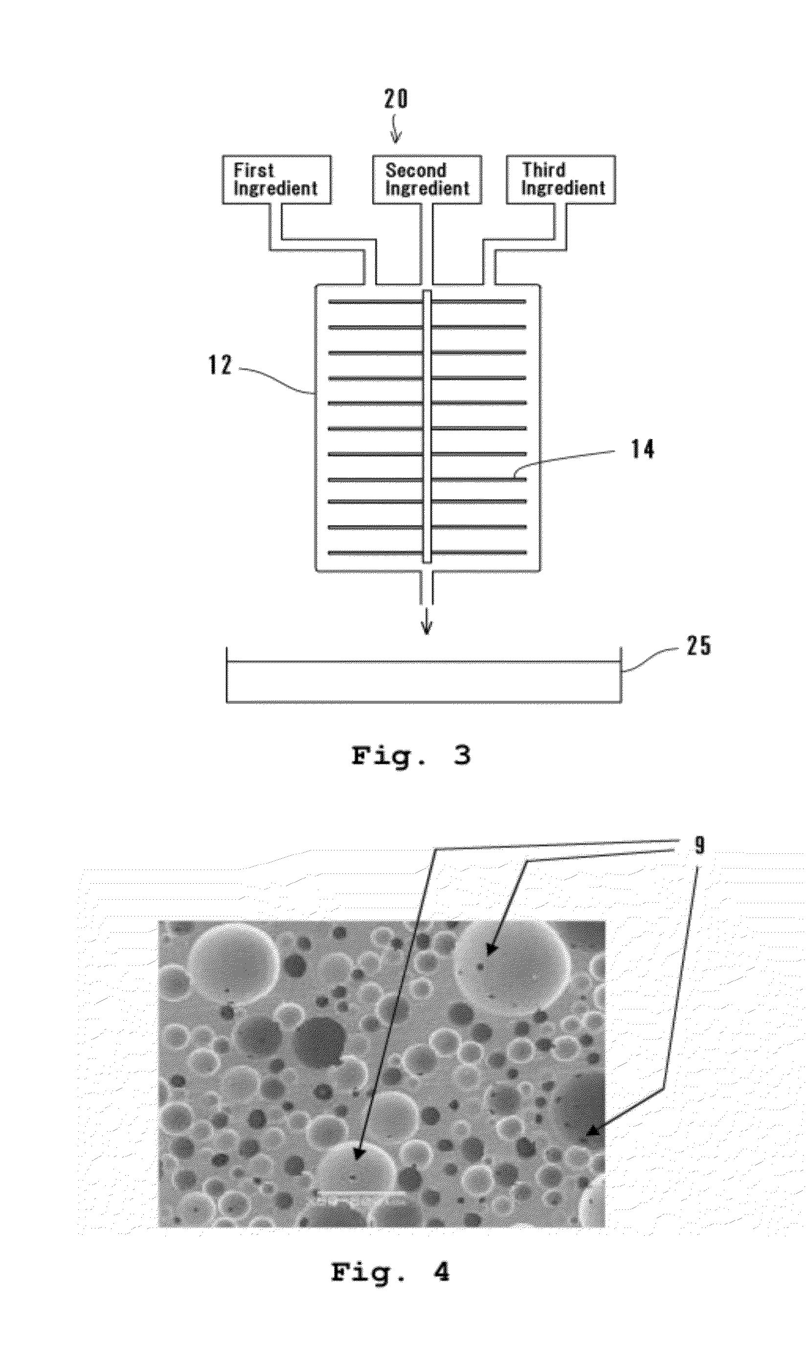
[0066]In Example 1, prepolymer of the first ingredient obtained by reacting 2,4-TDI, PTMG having a number average molecular weight of about 1000 and diethylene glycol was heated to 55 deg. C. and degassed under a reduced pressure. This prepolymer had an isocyanate containing amount of 9.6%. MOCA of the second ingredient was melted at 120 deg. C. and degassed under a reduced pressure. The dispersion of the third ingredient was obtained by mixing PTMG having a number average molecular weight of about 1000, water, catalyst (TOYOCAT-ET manufactured by Tosoh Corporation) and silicone-based surfactant (SH-193 manufactured by Dow Corning Toray Silicone Company Ltd.) at a ratio of 2.5 / 0.1 / 0.05 / 0.05. In this dispersion, a mixed ratio of the silicone-based surfactant falls upon 0.5 weight parts when converted to per one weight part of the water. After the first, second and third ingredients were degassed under a reduced pressure, they were supplied to the mixing tank 12 at a ratio of 79.0 / 18....

example 2

[0067]In Example 2, a polishing pad B of Example 2 was manufactured using the urethane sheet 2 in the same manner as Example 1 except that an addition ratio of the silicone-based surfactant was set to 0.03. At this time, a mixed ratio of the silicone-based surfactant falls upon 0.3 weight parts when converted to per one weight part of the water.

[0068](Control 1)

[0069]In Control 1, a polishing pad C of Control 1 was manufactured using the urethane sheet in the same manner as Example 1 except that an addition ratio of the silicone-based surfactant was set to 0.15. At this time, a mixed ratio of the silicone-based surfactant falls upon 1.5 weight parts when converted to per one weight part of the water.

[0070](Control 2)

[0071]In Control 2, a polishing pad D of Control 2 was manufactured using the urethane sheet in the same manner as Example 1 except that an addition ratio of the silicone-based surfactant was set to 0.01. At this time, a mixed ratio of the silicone-based surfactant falls...


PUM

PropertyMeasurementUnit
Lengthaaaaaaaaaa
Lengthaaaaaaaaaa
Timeaaaaaaaaaa

Abstract

A polishing pad capable of improving an affinity to polishing liquid and stabilizing polishing performance is provided. A polishing pad 10 is equipped with a urethane sheet 2. The urethane sheet 2 has a polishing surface P for polishing an object to be polished. The urethane sheet 2 is formed by a dry molding method and is formed by slicing a polyurethane foamed body which is obtained by reacting and curing mixed liquid in which an isocyanate-group containing compound, water, a foam control agent and a polyamine compound are mixed. Foams 3 are dispersed approximately uniformly inside the urethane sheet 2. Opened pores 4 which are opened parts of the foams 3 are formed at the polishing surface P. Inside the urethane sheet 2, the foams 3 formed adjacently to each other are communicated by communication holes 9, and the communication holes 9 are formed at a ratio of 800 holes/cm2 or more when observed from a side of the polishing surface P. Polishing liquid moves via the communication holes 9 and the foams 3.

Description

FIELD OF THE INVENTION[0001]The present invention relates to a polishing pad, a manufacturing method thereof and a polishing method, and in particular relates to a polishing pad in which a large number of foams are formed by a dry molding method and which has a resin foamed body where opened pores of the foams are formed at a polishing surface for polishing an object to be polished, a manufacturing method of the polishing pad and a polishing method using the polishing pad.DESCRIPTION OF THE RELATED ART[0002]Polishing work is being carried out by using a polishing pad for polishing a material for a semiconductor device, an electronic part or the like, especially, a surface (work surface) of a thin-type substrate (object to be polished) such as a Si substrate (silicon wafer), a GaAs (gallium arsenide) substrate, a substrate for glass, hard disk, LCD (liquid crystal display) or the like because these are required to have flatness. In the semiconductor device, as a degree of integration...

Claims


Application Information

Patent Timeline
IPC IPC(8): B24B1/00B24D18/00B24D11/00B24B37/24H01L21/304
CPCB24B37/24H01L21/02024B24D3/32
Inventor ITOYAMA, KOHKITAKAHASHI, DAISUKEUENO, JUNICHIKOBAYASHI, SYUICHI
Owner FUJIBO HLDG
Why Eureka
Try Eureka