
Concentration determination apparatus, concentration determination method, and program

a concentration determination and concentration technology, applied in the field of concentration determination apparatus, concentration determination method, and program, can solve the problems of complex and painful blood sample taking, infection risk, needle being left or infected during blood sugar measurement, etc., to accurately determine the concentration accurate measurement of the optical absorption amount of the target component, and non-invasive

Inactive Publication Date: 2012-04-26
SEIKO EPSON CORP +1
View PDF1 Cites 8 Cited by
  • Summary
  • Abstract
  • Description
  • Claims
  • Application Information

AI Technical Summary

Benefits of technology

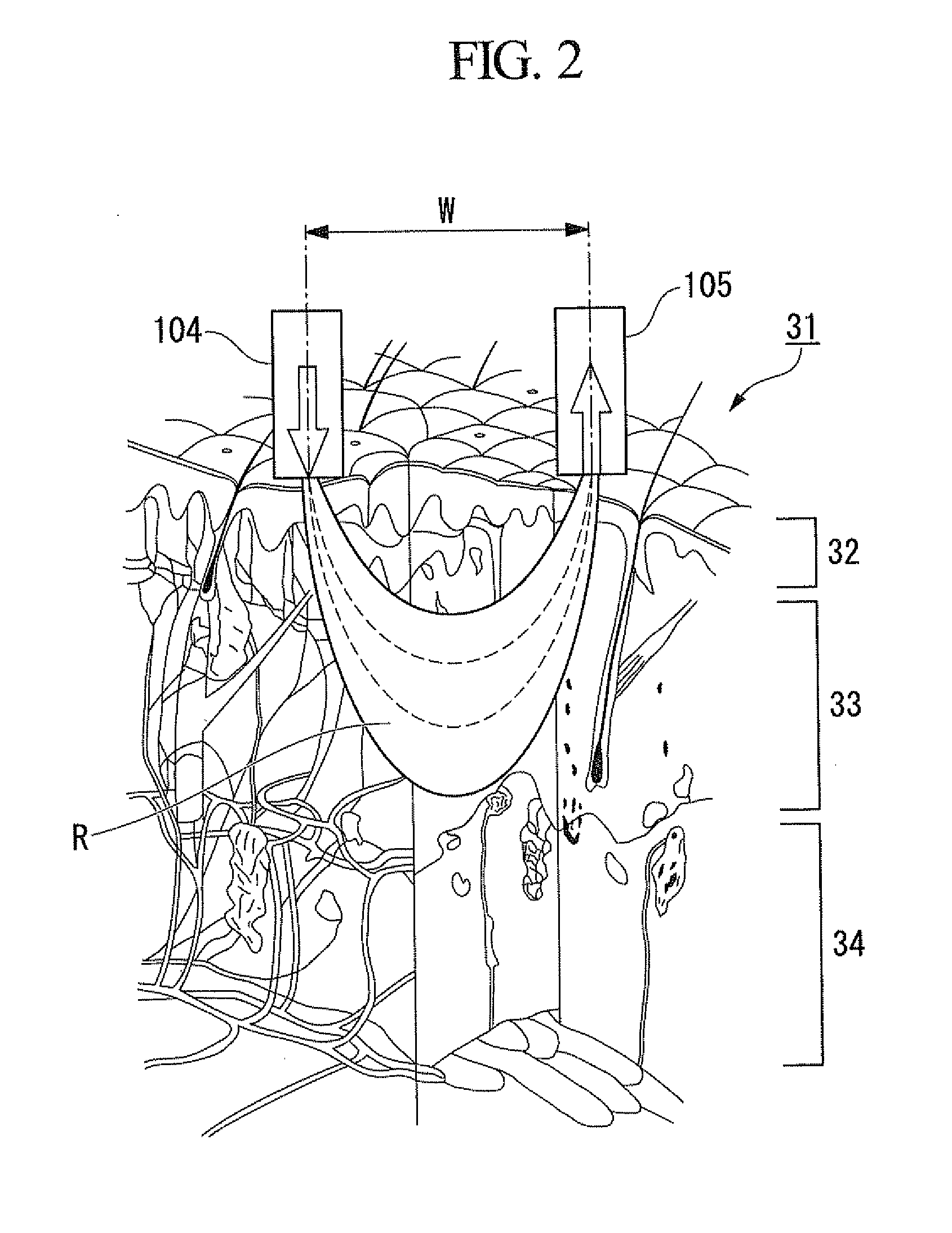
[0025]The present invention provides a concentration determination apparatus, a concentration determination method, and a program that can non-invasively and accurately determine the concentration of a target component in a specific layer by selecting an optical absorption coefficient of the specific layer, which is a specific portion in a combination close to an optical path length distribution of a structure of an observed object constituted by a plurality of layers.

Problems solved by technology

This method of measuring a blood sugar value has various problems, such as that taking a blood sample is complicated and painful, and poses a risk of infection.
However, since the injection needle is pushed into the vein, there are risks of the needle being left or infection during measurement of the blood sugar value.
However, it is not possible to measure only an absorption amount of light of a path passing through a specific depth in an apparatus for non-invasively measuring the blood sugar level by use of near-infrared continuous light in the related art.
Therefore, it is not possible to accurately determine a glucose concentration corresponding to blood sugar in the main components of the skin at a specific depth.
(3) When skin properties are classified from absorbance at a specific absorption wavelength of the subcutaneous fat, it is difficult to distinguish the dermis and the subcutaneous fat because fat is included in cells of the dermis and interstitial fluid.
However, in the apparatus of Japanese Patent No. 3931638, it is not possible to specify a portion of which a biological component concentration is determined using an infrared spectrum of the skin for the above-described reason, and therefore it is not possible to selectively measure absorbance in an optical path that passes through a specific portion, wherein stratum reticulare in which glucose is one of interstitial components in the dermis is designated as the specific portion.

Method used


Image

  • Concentration determination apparatus, concentration determination method, and program
  • Concentration determination apparatus, concentration determination method, and program
  • Concentration determination apparatus, concentration determination method, and program

Examples


first embodiment

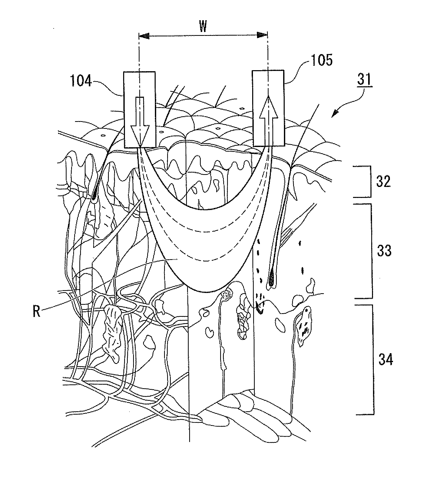
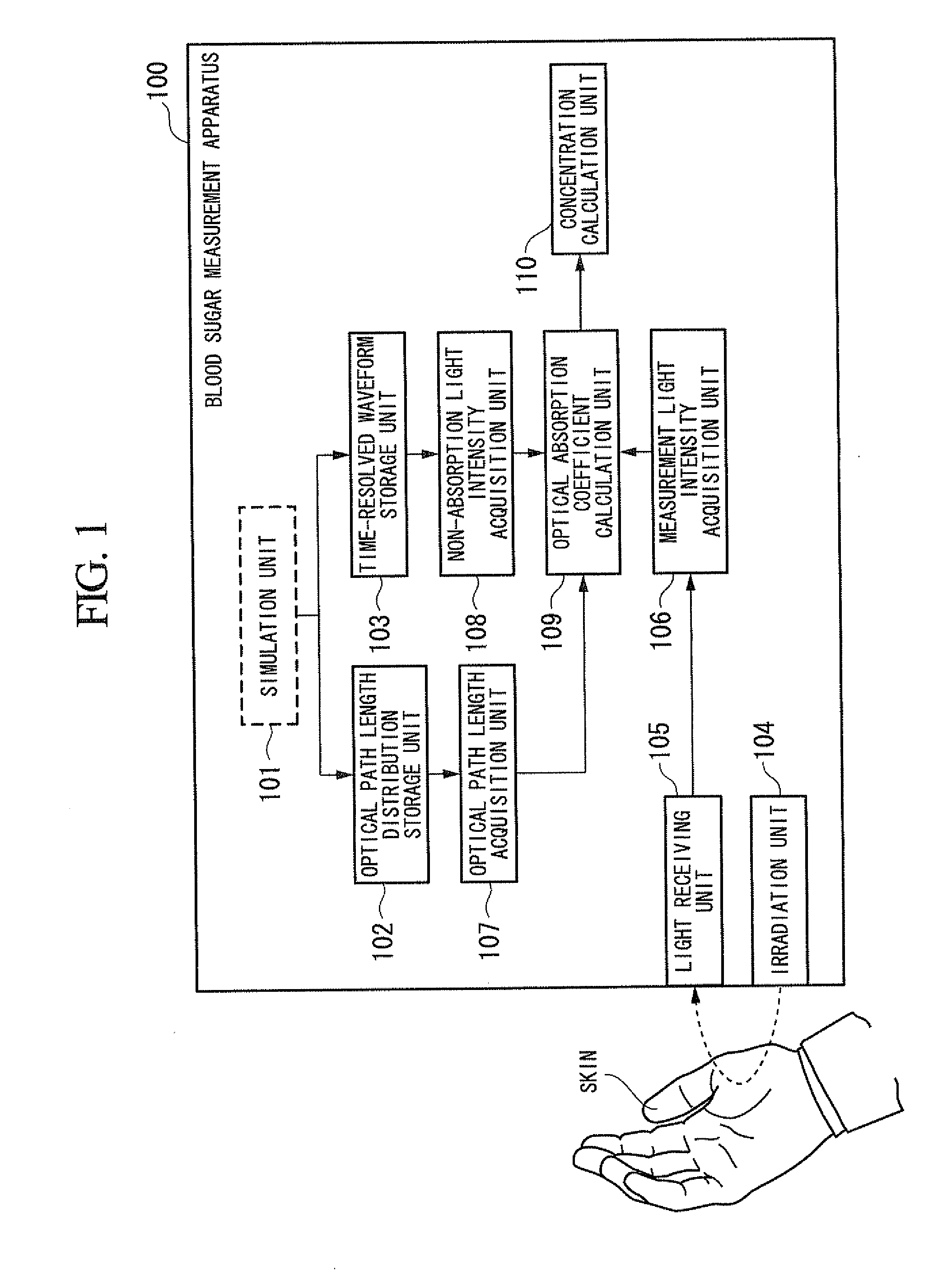
[0075]FIG. 1 is a schematic block diagram showing a configuration of a blood sugar value measurement apparatus 100 in accordance with a first embodiment of the present invention. A blood sugar measurement apparatus 100 includes a simulation unit 101, an optical path length distribution storage unit 102, a time-resolved waveform storage unit 103, an irradiation unit 104, a light receiving unit 105, a measurement light intensity acquisition unit 106, an optical path length acquisition unit 107, a non-absorption light intensity acquisition unit (a light intensity model acquisition unit) 108, an optical absorption coefficient calculation unit 109, and a concentration calculation unit 110.

[0076]The blood sugar measurement apparatus 100 measures a concentration of glucose (a target component) included in a dermis (a specific layer) of skin (an observed object).

[0077]The simulation unit 101 performs a simulation by irradiating light to a skin model having an optical absorption coefficient ...

second embodiment

[0144]The second embodiment of the present invention will be described in detail. A configuration of a blood sugar measurement apparatus according to the second embodiment is the same as that of the blood sugar measurement apparatus 100 according to the first embodiment, and operations of the measurement light intensity acquisition unit 106, the optical path length acquisition unit 107, the non-absorption light intensity acquisition unit 108, and the optical absorption coefficient calculation unit 109 are different.

[0145]FIG. 7 is a flowchart showing an operation in which the blood sugar measurement apparatus measures the blood sugar level.

[0146]First, when the blood sugar measurement apparatus 100 is operated, an irradiation unit 104 irradiates short-pulsed light of a wavelength λ1 to the skin (step S11). Here, the wavelength λ1 is one of a plurality of wavelengths for which the simulation unit 101 calculates optical path length distributions and time-resolved waveforms.

[0147]When ...

third embodiment

[0165]FIG. 8 is a schematic block diagram showing a configuration of a blood sugar measurement apparatus in accordance with a third embodiment of the present invention.

[0166]A difference of the blood sugar measurement apparatus 200 of this embodiment from the blood sugar measurement apparatus 100 of the first embodiment is that the blood sugar measurement apparatus 200 includes the irradiation unit 104, the light receiving unit 105, and a computer system 201, wherein the computer system 201 includes a storage unit 202 and a control unit (a central processing unit (CPU)) 203, the storage unit 202 executes functions of the optical path length distribution storage unit 102 and the time-resolved waveform storage unit 103 storing simulation results of the simulation unit 101, and the control unit (CPU) 203 executes functions of the measurement light intensity acquisition unit 106, the optical path length acquisition unit 107, the non-absorption light intensity acquisition unit 108, the o...


PUM


Abstract

A concentration determination apparatus may include: an irradiation unit that irradiates short-pulsed light to an observed object; a light receiving unit that receives light backscattered from the observed object; a light intensity acquisition unit that acquires an intensity distribution of the light; an optical path length distribution storage unit that stores a model of an optical path length distribution in each layer of the plurality of layers of the short-pulsed light; an optical path length acquisition unit that acquires the optical path length distribution of each layer; a time-resolved waveform storage unit that stores a model of a time-resolved waveform; a light intensity model acquisition unit that acquires a light intensity model; an integral interval calculation unit that calculates a time range of an area; an optical absorption coefficient calculation and acquisition unit that calculates and acquires an optical absorption coefficient; and a concentration calculation unit that calculates the concentration.

Description

BACKGROUND[0001]1. Technical Field[0002]The present invention relates to a concentration determination apparatus, a probe, a concentration determination method, and a program for non-invasively determining a concentration of a target component in an observed object in any of a plurality of light scattering medium layers in a living body.[0003]Priority is claimed on Japanese Patent Application No. 2010-235927 filed on Oct. 20, 2010, the contents of which are incorporated herein by reference.[0004]2. Description of the Related Art[0005]All patents, patent applications, patent publications, scientific articles, and the like, which will hereinafter be cited or identified in the present application, will hereby be incorporated by reference in their entirety in order to describe more fully the state of the art to which the present invention pertains.[0006]In recent years, diabetics in an age of gluttony continue to increase each year in Japan. Therefore, diabetics with nephritis also cont...

Claims


Application Information

Patent Timeline
IPC IPC(8): A61B5/1455G01N21/35G01N21/359
CPCA61B5/14532A61B2562/0242A61B5/1455
Inventor AMANO, KAZUHIKOSHIMIZU, KOICHI
Owner SEIKO EPSON CORP
Learn More