

Closable counter-measure compartments for a dispenser unit
a dispenser unit and counter-measure technology, applied in the direction of instruments, reflecting targets, apparatus for dispensing discrete objects, etc., can solve the problems of vehicle or dispenser structure damage, undesirable noise,
- Summary
- Abstract
- Description
- Claims
- Application Information
AI Technical Summary
Benefits of technology
Problems solved by technology
Method used
Image

Examples
second embodiment
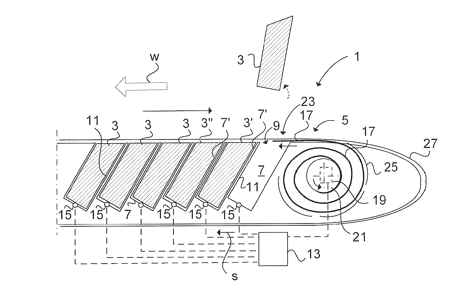
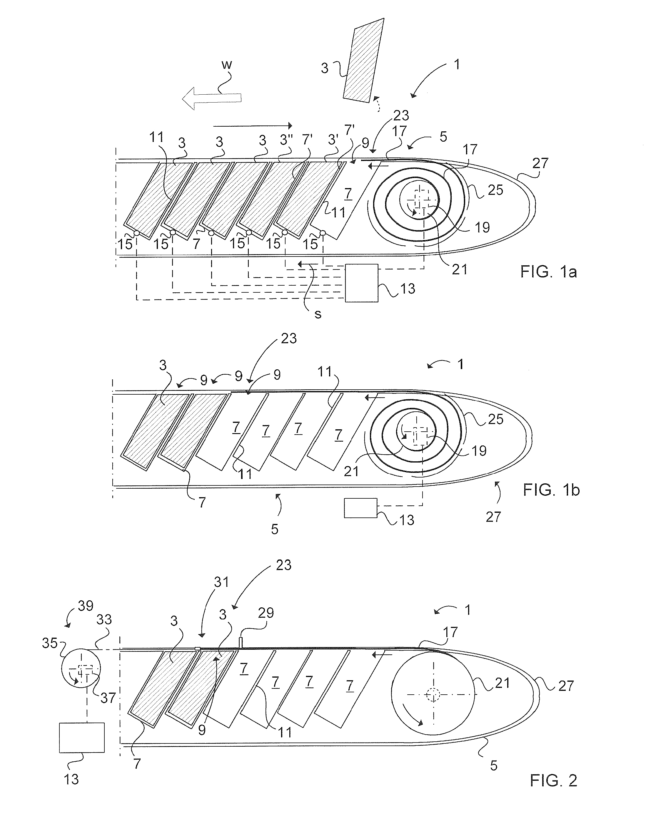
[0041]FIG. 2 illustrates the dispenser unit 1 wherein a spoiler 29 has been arranged on the outside of the flexible shutter 17 near the shutter's advancing end 23, i.e. the end of the elongated flexible shutter 17, which covers the compartment 7 from which the latest launched chaff 3 was stored. The distance from a forward edge 31 of the advancing end 23 to the spoiler 29 corresponds with the measurement of the opening 9 seen in the longitudinal direction of the dispenser unit 1. The flexible shutter 17 is also made of a frangible material. In this way, in case of malfunction wherein the flexible shutter 17 by mistake is driven over an opening 9 of a compartment 7 before the payload (here chaff 3) is launched from that particular compartment 7, the payload still can be launched from the dispenser unit 1. The chaff 3 will in that case be ejected from the compartment 7—through the flexible shutter 17—within an area of the flexible shutter 17 corresponding with the position of the actu...
third embodiment
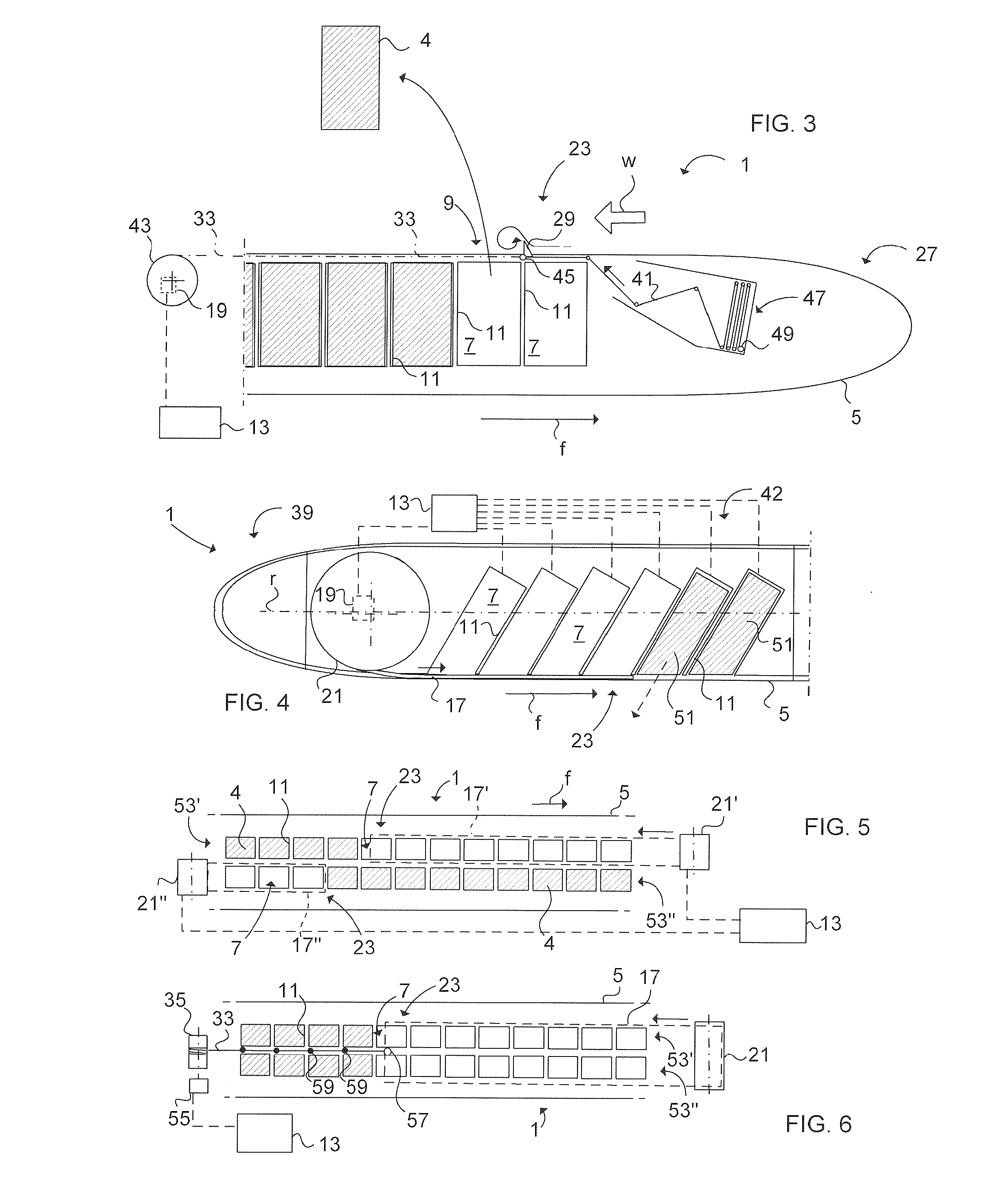
[0042]FIG. 3 schematically illustrates a cross section of a dispenser unit 1 according to a The door means is arranged as a folding curtain 41 in the nose cone 27. In a fully folded state (in an initial position) a not bulky package can thus be achieved. The driving means is in this case a draw wire 33 connected to a motor driven roller 43 arranged for drawing the folding curtain 41 step wise in steps over each compartment's 7 opening 9 depending on whether the next payload 4 has been launched from that particular compartment 7. This action is controlled by the control unit 13. The draw wire 33 is thus also connected via a coupling 45 to the folding curtain 41. A spoiler 29 is arranged onto the advancing end 23 of the folding curtain 41. The advancing end 23 is defined as the end of the folding curtain 41 being nearest the coupling 45 and an opposite end 47 of the folding curtain 41 is defined as the end fastened to a holder 49 arranged in the nose cone 27. The spoiler 29 projects ...
fourth embodiment
[0043]FIG. 4 schematically illustrates a cross section of a dispenser unit 1 wherein the storing axle 21 and the electrical motor 19 are arranged in the back part 39 of the dispenser unit 1 for storing and driving the shutter 17. In this way no driving means has to be arranged in the nose cone, whereby the nose cone can be designed with any aerodynamic body required. In FIG. 4 four IR flares 51 have been launched. The first of which being launched was situated in the rearmost compartment 7, which thereafter was sealed by the advancing end 23 of the shutter 17. A stepwise motion was performed by means of the control unit 13 in such way that the advancing end 23 was stopped for not covering the next IR flare 51 to be launched. Thereafter the control unit 13 fed a signal to launch this next IR flare 51 and immediately thereafter the control unit 13 gave a signal to the electrical motor 19 to drive the shutter 17 such that the advancing end 23 covered that particular compartment 7 from...
PUM
 Abstract
Description
Claims
Application Information