
Steam-Hydrocarbon Reforming with Limited Steam Export

a technology of steam hydrocarbon and export, which is applied in the direction of liquid-gas reaction process, chemical apparatus and processes, organic chemistry, etc., can solve the problems of high cost, high pipeline system cost, additional capital expenditure, etc., and achieve the effect of limited or reducing steam expor

Active Publication Date: 2012-05-03
AIR PROD & CHEM INC
View PDF0 Cites 6 Cited by
  • Summary
  • Abstract
  • Description
  • Claims
  • Application Information

AI Technical Summary

Benefits of technology

[0025]wherein the reactor is provided with a heat transfer surface area, the heat transfer surface area for exchanging heat indirectly between the reformate and the reformed gas during the reacting of the reformate in the reactor wherein the heat transfer surface area is effective to decrease the temperature of the reformed gas from the second inlet temperature ranging from 800° C. to 975° C. to the second outlet temperature ranging from 675° C. to 925° C. or ranging from 700° C. to 850° C. and to maintain the first outlet temperature of the reformate between 575° C. and 725° C.
[0045]a reactor having the first inlet in downstream fluid flow communication with the prereformer for receiving the reformate from the prereformer, the reactor containing the reforming catalyst, the reactor having the first outlet in upstream fluid flow communication with the inlet ends of the plurality of reformer tubes, the reactor having the second inlet in downstream fluid flow communication with the outlet ends of the plurality of reformer tubes for receiving the reformed gas from the plurality of reformer tubes, the reactor having the second outlet for withdrawing the reformed gas at the second outlet temperature, and the reactor having the heat transfer surface area for exchanging heat indirectly between the reformate and the reformed gas wherein the heat transfer surface area is effective to decrease the temperature of the reformed gas from the second inlet temperature ranging from 800° C. to 975° C. to the second outlet temperature ranging from 675° C. to 925° C. or ranging from 700° C. to 850° C. and to maintain the first outlet temperature of the reformate between 575° C. and 725° C. when the reformate is introduced into the first inlet of the reactor at the first inlet temperature ranging from 575° C. to 725° C. or ranging from 600° C. to 700° C.

Problems solved by technology

However, exporting steam requires expensive pipeline systems including control and safety valves, steam traps, heat tracing, etc.
Both options require additional capital expenditure and can be cost prohibitive for projects where there is no customer willing to buy the steam at a reasonable cost, or power cannot be produced competitively.
For small hydrogen production units where steam export is not justified, a portion of the excess steam is often used in the process less efficiently or vented.
The hydrogen plant may be designed with less heat recovery equipment resulting in a less efficient plant.
When credit for the steam produced cannot be reasonably factored in to the efficiency of the synthesis gas generating facility, methods are required to lessen the impact on plant efficiency.

Method used


Image

  • Steam-Hydrocarbon Reforming with Limited Steam Export
  • Steam-Hydrocarbon Reforming with Limited Steam Export
  • Steam-Hydrocarbon Reforming with Limited Steam Export

Examples


example 1

Comparative Example

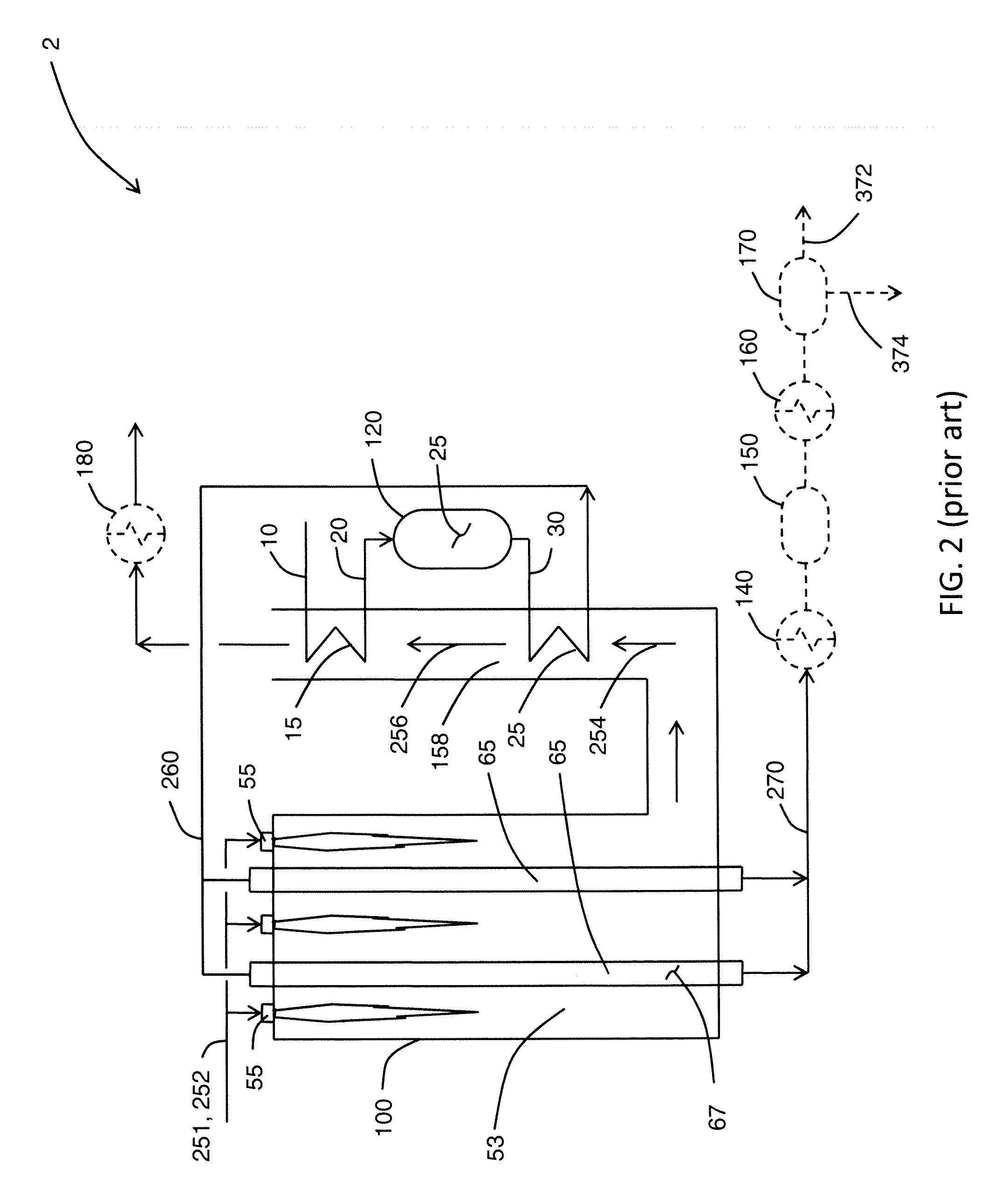
[0091]FIG. 2 illustrates a process flow diagram 2 for a prior art configuration.

[0092]Prereformer feed gas 10 consisting of steam and natural gas with a steam-to-carbon molar ratio of 2.5 is heated in heat exchanger 15 and the heated prereformer feed gas 20 is reacted in prereformer 120 over prereformer catalyst 25. Reformate 30 is withdrawn from the prereformer 120 and heated in heat exchanger 25 to form a heated reformate which is passed to the plurality of reformer tubes 65 as reformer feed gas 260. Reformer feed gas 260 is reacted over reforming catalyst 67 and withdrawn from the plurality of reformer tubes 65 as reformed gas 270. Reformed gas 270 is passed to boiler 140 to generate steam thereby cooling reformed gas 270. The cooled reformed gas 270 is passed to shift reactor 150 to convert CO to CO2 and form additional H2 in the reformed gas. The shifted reformed gas is passed to air cooler 160 to condense out water and prepare the reformed gas pressure swing...

example 2

Comparative Example with Reduced Steam Export

[0100]The process flow diagram in FIG. 2 also applies for Example 2. The amount of steam formed is decreased by increasing the air preheat temperature. The air preheat temperature is increased by preheating the air in two stages. Example 1 has a single stage of aft preheat, whereas example 2 has two stages of air preheat. Otherwise example 2 is the same as example 1. The process was optimized for an air preheat temperature provided by the two-stage air preheat to achieve the lowest Net Specific Energy while keeping the mole fraction ratio, R, the same as in example 1.

[0101]The steam-to-carbon molar ratio, S / C, for example 2 was essentially the same as for example 1.

[0102]The amount of excess steam produced in example 2 was significantly less than for example 1 as demonstrated by the ratio of steam used for reforming to the total steam produced in the process, S / ST. S / ST for example 2 is 0.64 compared to 0.45 for example 1.

[0103]While the ...

example 3

Gas Heat Exchange Reformer and Reduced Steam Export

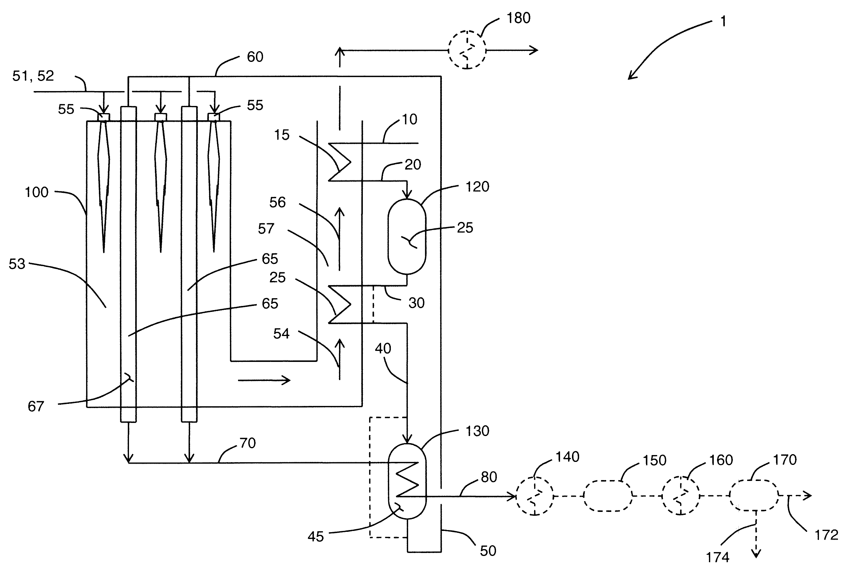
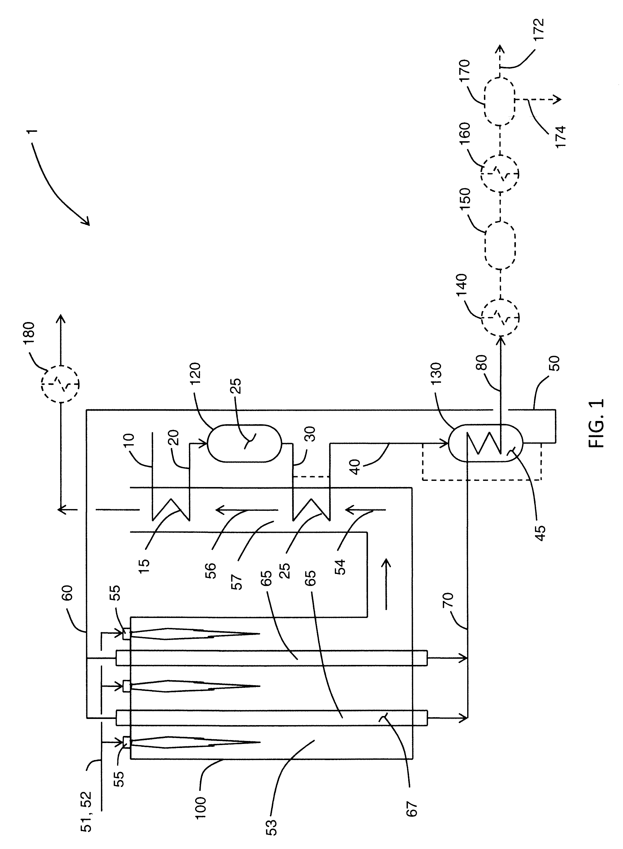
[0104]FIG. 1 illustrates a process flow diagram 1 for example 3. Like example 2, example 3 also uses two stages of air preheat.

[0105]Example 3 includes the gas heat exchange reformer 130 and the process was optimized to provide the lowest net specific energy, NSE, for a specified reformate inlet temperature of 649° C. and a specified reformed gas outlet temperature of 788° C. while keeping the mole fraction ratio, R, less than those in examples 1 and 2. The mole fraction ratio, R, for example 3 was not maintained at the same value as for examples 1 and 2 because the supplemental fuel value goes to zero in the optimization, which is a situation those skilled in the art know to avoid. The mole fraction ratio, R, is affected by the steam-to-carbon molar ratio, which can be reduced to 2.3 while providing a mole fraction ratio, R, of about 1.12. The temperatures in and out of the gas heat exchange reformer 130 are limited according to th...


PUM


Abstract

A steam-hydrocarbon reforming process and apparatus wherein reformate from a prereformer is reacted in a gas heated reformer which is heated by reformed gas from a primary reformer. Reformate from the gas heated reformer is passed to the primary reformer as feed gas.

Description

BACKGROUND[0001]The present disclosure relates to steam-hydrocarbon reforming. Hydrogen and / or synthesis gas are generated by steam-hydrocarbon reforming. Steam-hydrocarbon reforming processes typically generate steam as a means to recover heat and improve the process efficiency. The present disclosure more particularly relates to steam-hydrocarbon reforming with limited or reduced steam generation as compared to conventional plants.[0002]Synthesis gas is used to produce products such as ammonia, methanol and hydrogen. Synthesis gas is generated by high temperature processes where a lot of waste heat is available. The waste heat is generally used to generate steam and helps to improve the overall efficiency of the synthesis gas facility. In typical facilities, the amount of steam generated from the waste heat significantly exceeds the amount of steam needed for reforming of a hydrocarbon feed in a steam-hydrocarbon reformer. The excess steam is exported or may be used to generate po...

Claims


Application Information

Patent Timeline
IPC IPC(8): C01B3/22B01J8/06
CPCC01B3/382C01B3/384C01B2203/0233C01B2203/0805C01B2203/84C01B2203/0827C01B2203/142C01B2203/143C01B2203/0816
Inventor PHAM, HOANH NANGPENG, XIANG-DONGNATARAJ, SHANKARENEVER, MICHAEL
Owner AIR PROD & CHEM INC
Learn More