Light amount detecting apparatus, and light amount information processing apparatus

Active Publication Date: 2012-05-03
PIONEER MICRO TECH CORP +1
View PDF1 Cites 7 Cited by
  • Summary
  • Abstract
  • Description
  • Claims
  • Application Information

AI Technical Summary

Benefits of technology

[0037]According to this aspect, by a delay action for delaying demodulation timing by the predetermined time performed by the delaying device, it is possible to effectively prevent the residual of the harmonic component of the carrier frequency in the demodulation, which is caused by a time difference between modulation timing by the modulating device and the demodulation timing by the demodulating device. As a result, it is possible to effectively suppress a high-frequency noise generated in the demodulation, and it is possible to realize a further improvement in the S/N ratio of the light detection signal.
[0038]In another aspect of the light amount detecting apparatus of the present invention, it is further provided with a high-frequency pass filtering device for removing a low-frequency noise of the voltage signal of the voltage modulated.
[0039]According to this aspect, since the low-frequen

Problems solved by technology

In the aforementioned patent document 1 or the like, since the reverse bias voltage is applied in the photodiode, the capacitance between a P terminal and an N terminal can be reduced by the application of the reverse bias voltage; however, as an evil influence, even without the amount of light inputted, a current flowing in an opposite direction, i.e. a dark current, is generated,

Method used


Image

  • Light amount detecting apparatus, and light amount information processing apparatus
  • Light amount detecting apparatus, and light amount information processing apparatus
  • Light amount detecting apparatus, and light amount information processing apparatus

Examples


Example

First Embodiment

[0057]

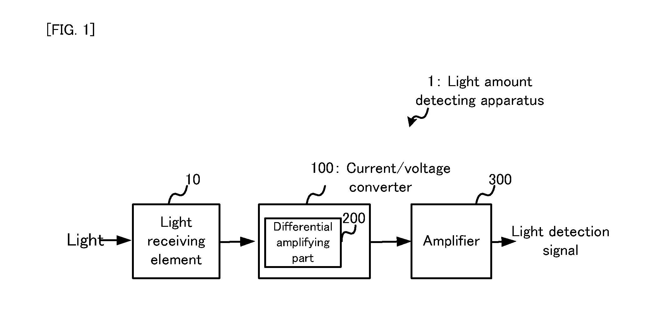
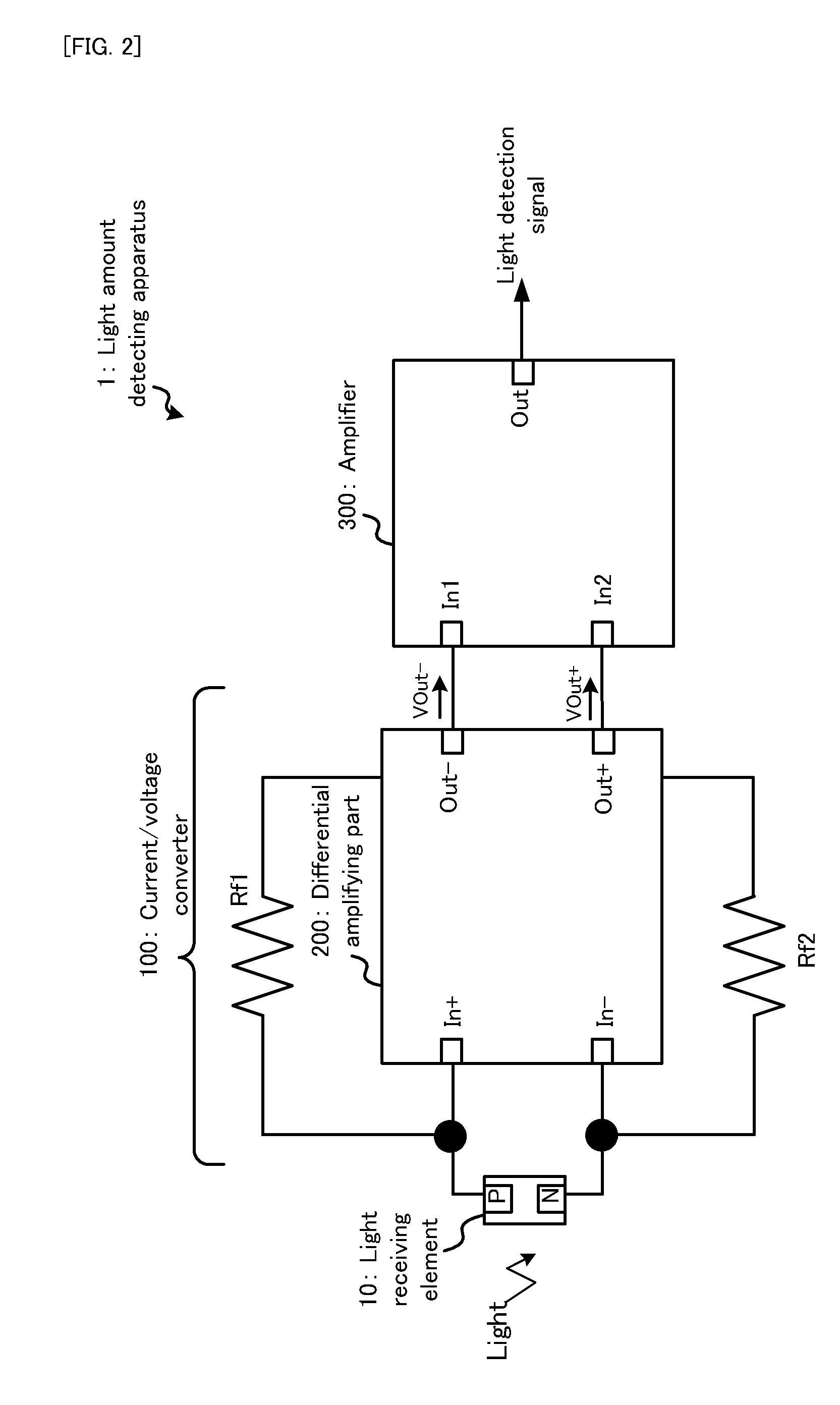
[0058]Firstly, with reference to FIG. 1 and FIG. 2, the basic configuration of a first embodiment of the present invention will be explained. FIG. 1 is a block diagram conceptually showing the entire structure of a light amount detecting apparatus 1 in a first embodiment. FIG. 2 is a block diagram schematically showing the detailed structure of the light amount detecting apparatus 1 in the first embodiment.

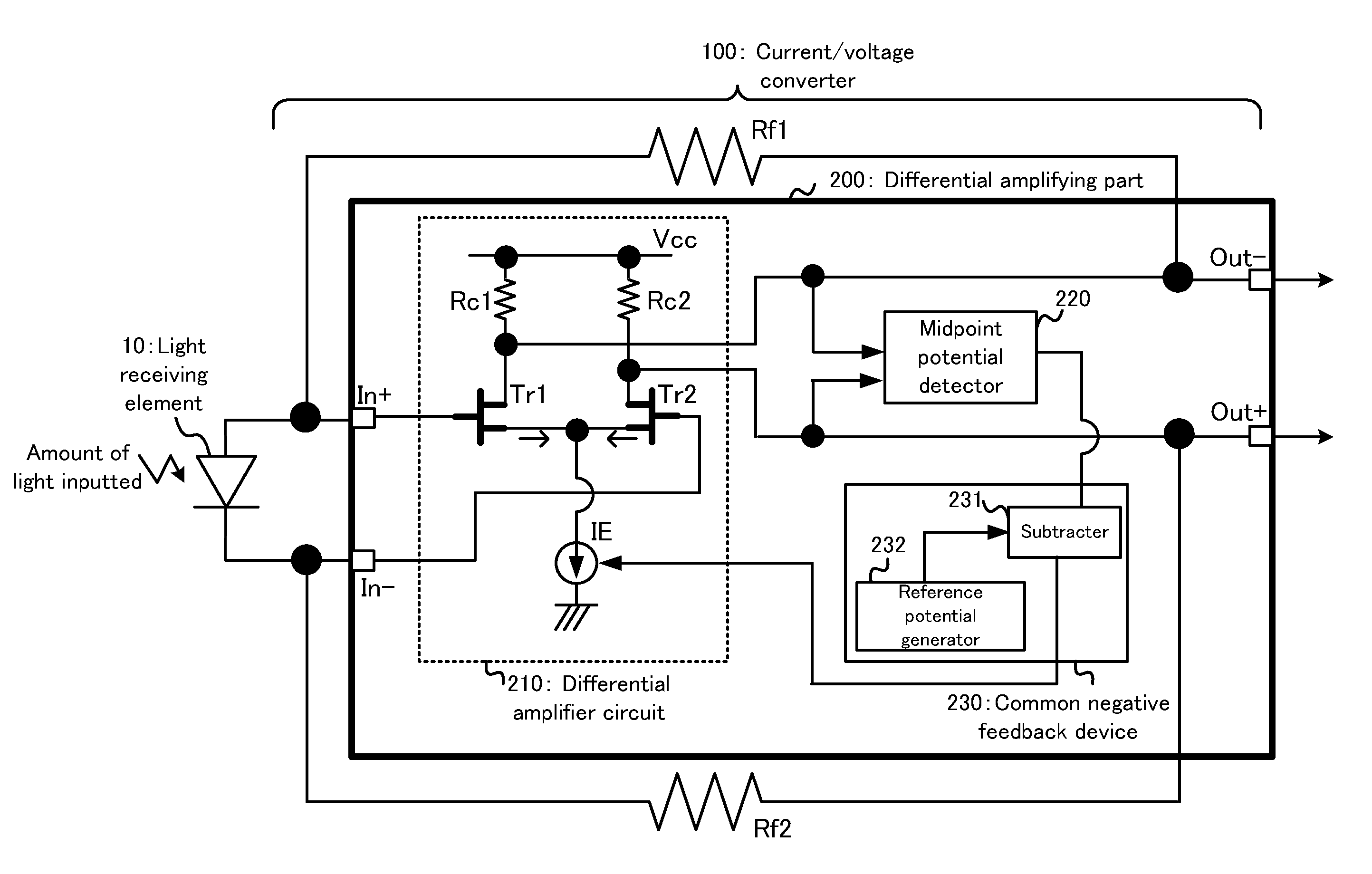
[0059]As shown in FIG. 1 and FIG. 2, the light amount detecting apparatus 1 in the first embodiment is provided with a light receiving element 10, a current / voltage converter 100 including a differential amplifying part 200, and an amplifier 300. The current / voltage converter 100 is provided with the differential amplifying part 200 and feedback resistors Rf1 and Rf2. The amplifier 300 is provided with input terminal In1 and In2 and an output terminal Out.

[0060]The light receiving element 10 receives a small amount of light inputted from the exterior and outp...

Example

Second Embodiment

Amplifier

[0107]Next, the detailed structure of an amplifier 300a in a second embodiment will be explained. FIG. 6 is a circuit diagram schematically showing the detailed structure of the amplifier 300a in the second embodiment. Incidentally, in the amplifier 300a in the second embodiment, substantially the same constituents as those of the amplifier 300 in the first embodiment described above will carry the same reference numerals, and the explanation thereof will be omitted, as occasion demands. Moreover, since a light receiving element 10 and a current / voltage converter 100 in the second embodiment are substantially the same as the light receiving element 10 and the current / voltage converter 100 in the first embodiment, their explanation will be limited for convenience sake.

[0108]As shown in FIG. 6, the amplifier 300a in the second embodiment is provided with operational amplifiers OP1 and OP2, feedback resistors R2 and R3, a common input resistor R1, low pass fil...

Example

Third Embodiment

[0111]Next, with reference to FIG. 7 to FIG. 10, a light amount detecting apparatus 1 in a third embodiment will be explained. Incidentally, regarding the constituents in the third embodiment, the constituents which are substantially the same as those in the first and second embodiments described above will carry the same reference numerals, and the explanation thereof will be omitted as occasion demands.

[0112]

[0113]Firstly, with reference to FIG. 7 and FIG. 9, the detailed structure of a current / voltage converter 100b in the third embodiment and modulation on the current / voltage converter 100b will be explained. FIG. 7 is a block diagram schematically showing the detailed structure of the current / voltage converter 100b in the third embodiment. FIG. 9 is waveform diagrams along a time axis showing a detection current Idt of a light receiving element, detection voltages Vout+ and Vout−, control signals of a switch action SWP1, SWP2, and SWP3, and a light detection sig...


PUM


Abstract

A light amount detecting apparatus includes: a photoelectric converting element converting quantity of light inputted to current; a current/voltage converting device having a positive input terminal connected to a first terminal of the photoelectric converting element, a negative input terminal connected to a second terminal of the photoelectric converting element, a negative output terminal for reversing polarity of a current inputted to the positive input terminal and outputting it as a voltage, a positive output terminal for reversing polarity of a current inputted to the negative input terminal and outputting it as a voltage, a first negative feedback resistor connecting the positive and negative output terminals, and a second negative feedback resistor connected between the negative and positive output terminals, the current/voltage converting device setting the photoelectric converting element in zero bias and converting the converted current to the voltage; and an amplifying device for amplifying the converted voltage.

Description

TECHNICAL FIELD[0001]The present invention relates to, for example, a light amount detecting apparatus such as a photoelectric converting apparatus for converting a small amount of light to an electrical signal, and a light amount information processing apparatus for processing a light detection signal according to the small amount of light.BACKGROUND ART[0002]As this type of apparatus, a patent document 1 or the like discloses a technology about a light receiving circuit for high-speed communication used for optical communication. Specifically, it discloses a technology in which a reverse bias voltage is applied to a photodiode by a bias element, thereby reducing capacitance between both terminals of the photodiode, and broadening a light detecting band.PRIOR ART DOCUMENTPatent Document[0003]Patent document 1: Japanese Patent Application Laid Open No. Hei 6-224652[0004]Patent document 2: Japanese Patent Application Laid Open No. 2000-261385[0005]Patent document 3: Japanese Patent A...

Claims


Application Information

Patent Timeline
IPC IPC(8): G05F1/10
CPCG01J1/44H03F3/082H03F3/087H03F3/45183H03F3/45475H03F3/4565H03F2203/45082H03F2203/45138H03F2203/45528H03F2203/45702
Inventor TATEISHI, KIYOSHIHANADA, YOSHIHIRONAKAMURA, MICHIAKI
Owner PIONEER MICRO TECH CORP
Why Eureka
Try Eureka