Method for producing sintered ferrit magnet, and sintered ferrite magnet

a technology of ferrite magnets and ferrites, which is applied in the direction of magnets, magnetic materials, magnetic bodies, etc., can solve the problems of poor squareness ratio, insufficient high, and substantially the same level of magnetic properties, and achieve high br and squareness ratio hk/hcj, improve hcj, and improve the effect of hcj

Active Publication Date: 2012-05-03
HITACHI METALS LTD
View PDF7 Cites 18 Cited by
  • Summary
  • Abstract
  • Description
  • Claims
  • Application Information

AI Technical Summary

Benefits of technology

[0017]Accordingly, an object of the present invention is to provide a sintered Ca—La—Co ferrite magnet having extremely improved HcJ while maintaining high Br and squareness ratio H

Problems solved by technology

However, it has magnetic properties on substantially the same levels as those of conventional Ba ferrite, not sufficiently high.
In addition, having an extremely poor squareness ratio, it does not meet high coercivity and a high squareness ratio simultaneously, failing to be used for various applications such as motors, etc.
Though HcJ is improved by the method of JP 2007-123511 A, cost increase is unavoidable due to increase in the number of production steps.
Particularly, Sr—La—Co ferrite containing expensive elements such as Co, La, etc. as indispensable components suffers a higher material cost than conventional Sr ferrite.
Higher production cost deprives sintered ferrite magnets of the most important economic advantages, failing to meet cost requirements in the market.
However, the Ca—La—Co ferrites of JP 2006-104050 A, WO 2007/060757 and WO 2007/07781

Method used


Image

  • Method for producing sintered ferrit magnet, and sintered ferrite magnet
  • Method for producing sintered ferrit magnet, and sintered ferrite magnet
  • Method for producing sintered ferrit magnet, and sintered ferrite magnet

Examples


example 1

[0120]CaCO3 powder, La(OH)3 powder, Fe2O3 powder and CO3O4 powder were mixed to have the formula of Ca1-x-yLaxAyFe2n-zCOzO19-δ, wherein x=0.5, y=0, z=0.3, n=5.2, and 6≧0, and 0.1% by mass of H3BO3 powder was added to the total amount (100% by mass) of the mixed powders to produce a starting material powder. This starting material powder was mixed by a wet ball mill for 4 hours, and granulated by drying. It was calcined at 1300° C. for 3 hours in the air, and the calcined body was coarsely pulverized by a hammer mill to obtain coarse powder.

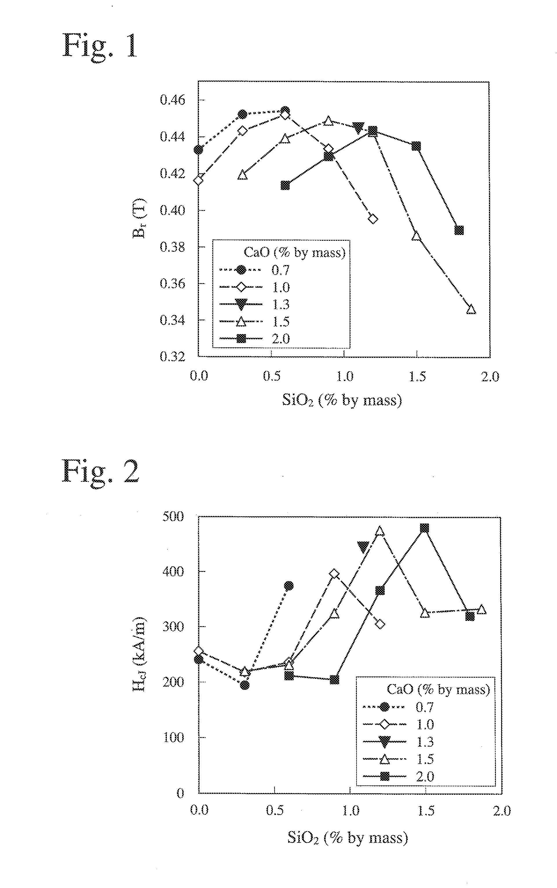
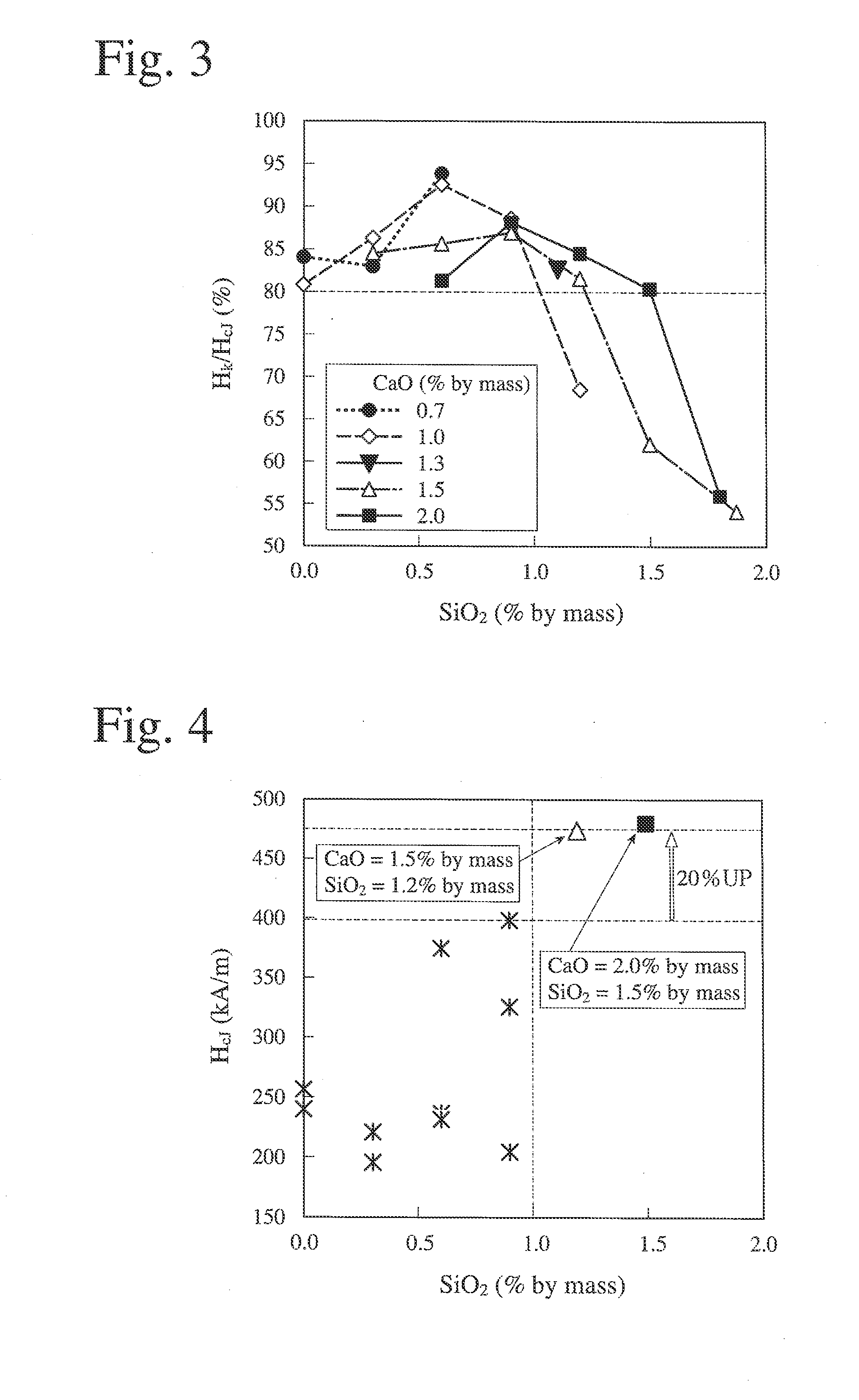
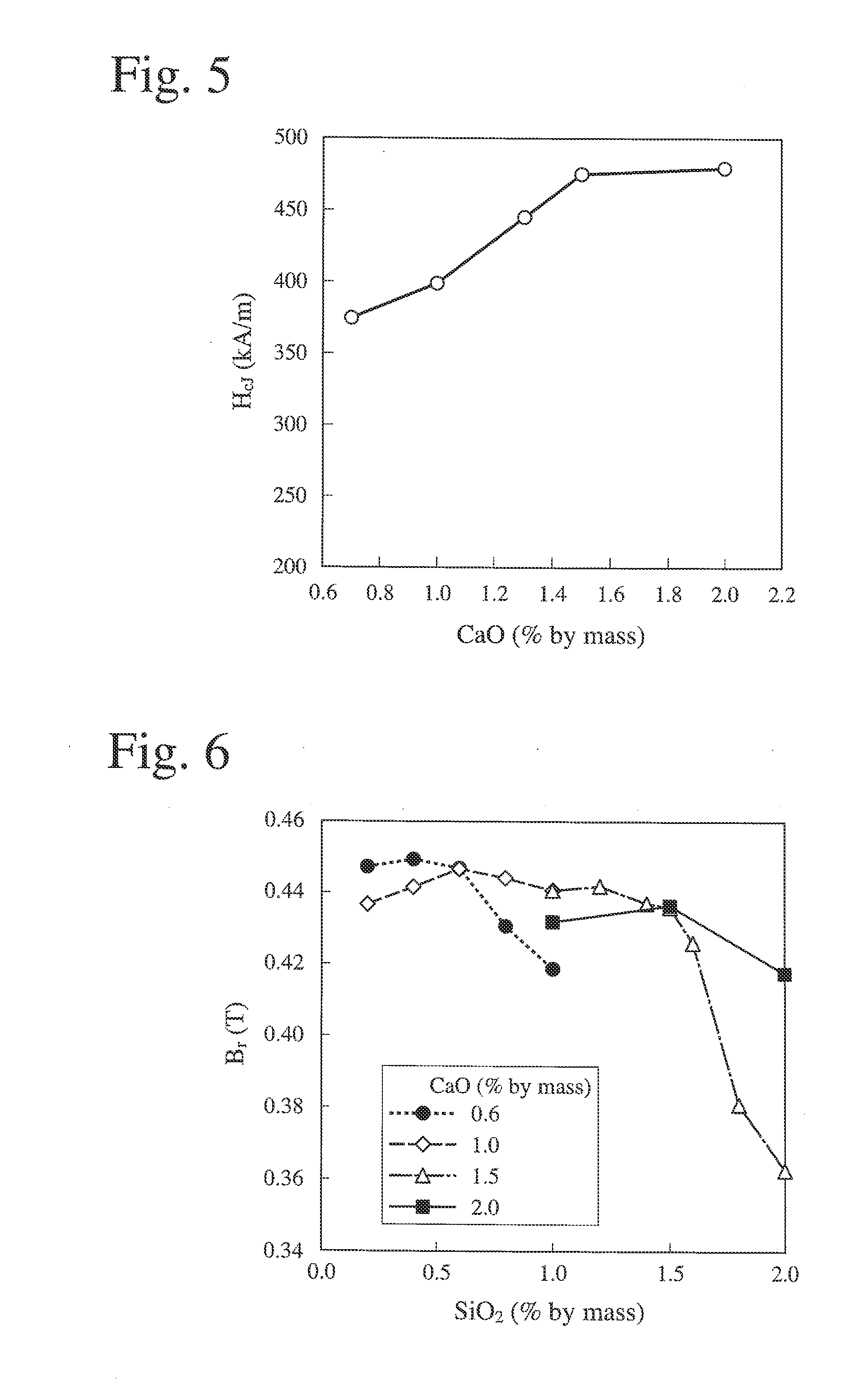
[0121]SiO2 powder and CaCO3 powder (calculated as CaO) were added in the amounts shown in Table 1 to the above coarse powder, and fine pulverization was conducted by a wet ball mill using water as a solvent until its average particle size (measured by an air permeation method) became 0.55 μm. Each of the resultant fine powder slurries was molded in a magnetic field of about 1.3 T under pressure of about 50 MPa with a compression direction parallel...

example 2

[0129]Sintered magnets were produced in the same manner as in Example 1, except that SiO2 powder and CaCO3 powder (calculated as CaO) were added in the amounts shown in Table 3 to a composition having the formula of Ca1-x-yLaxAyFe2n-zCOzO19-δ, wherein x=0.5, y=0, z=0.2, n=4.8, and δ≧0.

[0130]The sintered magnets were measured with respect to a residual magnetic flux density Br, coercivity HcJ, and a squareness ratio Hk / HcJ. The measurement results are shown in FIGS. 6-8. As in Example 1, in FIGS. 6-8, the axes of abscissas represent the amount (% by mass) of SiO2 added, and the axes of ordinates represent a residual magnetic flux density Br (T) (FIG. 6), coercivity HcJ (FIG. 7), and a squareness ratio Hk / HcJ (FIG. 8), data at the same CaO content being connected by a straight line.

TABLE 3SampleCaOSiO2No.(% by mass)(% by mass)CaO / SiO22010.60.23.002020.60.41.502030.60.61.002040.60.80.752050.61.00.602061.00.25.002071.00.42.502081.00.61.672091.00.81.252101.01.01.002111.51.01.50 212*1.51....

example 3

[0134]Sintered magnets were produced in the same manner as in Example 1, except that SiO2 powder and CaCO3 powder (calculated as CaO) were added in the amounts shown in Table 4 to a composition having the formula of Ca1-x-yLaxAyFe2n-zCOzO19-δ, wherein x=0.5, y=0, z=0.25, n=5.0, and δ≧0.

[0135]The sintered magnets were measured with respect to a residual magnetic flux density Br, coercivity HcJ, and a squareness ratio Hk / HcJ. The measurement results are shown in FIGS. 10-12. As in Example 1, in FIGS. 10-12, the axes of abscissas represent the amount (% by mass) of SiO2 added, and the axes of ordinates represent a residual magnetic flux density Br (T) (FIG. 10), coercivity HcJ (FIG. 11), and a squareness ratio Hk / HcJ (FIG. 12). To investigate influence by the Co content (z) in FIGS. 10-12, Samples 111-115 in Example 1 and Samples 211-217 in Example 2 were plotted, and data at the same Co content (z) were connected by a straight line.

TABLE 4SampleCaOSiO2No.(% by mass) (% by mass)CaO / SiO...


PUM

PropertyMeasurementUnit
Fractionaaaaaaaaaa
Percent by massaaaaaaaaaa

Abstract

A sintered ferrite magnet comprising (a) a ferrite phase having a hexagonal M-type magnetoplumbite structure comprising Ca, an element R which is at least one of rare earth elements and indispensably includes La, an element A which is Ba and/or Sr, Fe, and Co as indispensable elements, the composition of metal elements of Ca, R, A, Fe and Co being represented by the general formula of Ca1-x-yRxAyFe2n-zCoz, wherein the atomic ratios (1-x-y), x, y and z of these elements and the molar ratio n meet the relations of 0.3≦(1-x-y)≦0.65, 0.2≦x≦0.65, 0≦y≦0.2, 0.03≦z≦0.65, and 4≦n≦7, and (b) a grain boundary phase indispensably containing Si, the amount of Si being more than 1% by mass and 1.8% or less by mass (calculated as SiO2) based on the entire sintered ferrite magnet, and its production method.

Description

FIELD OF THE INVENTION[0001]The present invention relates to a method for producing a sintered ferrite magnet, and a sintered ferrite magnet.BACKGROUND OF THE INVENTION[0002]Sintered ferrite magnets are used in various applications such as motors, power generators, speakers, etc. Known as typical sintered ferrite magnets are Sr ferrite (SrFe12O19) and Ba ferrite (BaFe12O19) each having a hexagonal M-type magnetoplumbite structure. These sintered ferrite magnets are produced from starting materials comprising iron oxide, carbonates of strontium (Sr) or barium (Ba), etc. by a powder metallurgy method at a relatively low cost.[0003]Recently, to provide smaller, lighter-weight, higher-performance electronic parts for automobiles, parts for electric appliances, etc. for environmental advantages, sintered ferrite magnets are required to have higher performance. Particularly desired for motors for automobiles are sintered ferrite magnets having, in addition to high residual magnetic flux d...

Claims


Application Information

Patent Timeline
IPC IPC(8): H01F7/02H01F41/02
CPCC04B35/2633H01F7/02C04B2235/3208C04B2235/3213C04B2235/3215C04B2235/3224C04B2235/3227C04B2235/3229C04B2235/3275C04B2235/3277C04B2235/3409C04B2235/3418C04B2235/44C04B2235/442C04B2235/767C04B2235/85H01F1/11H01F1/348H01F41/0266C01G49/0054C01G51/68C01P2002/76H01F1/0557C01P2006/42C04B35/2641
Inventor ODA, ETSUSHIKOBAYASHI, YOSHINORI
Owner HITACHI METALS LTD
Why Eureka
Try Eureka