Flameless impingement preheating furnace

a furnace and flameless technology, applied in the field of flameless impingement preheating furnaces, can solve the problems of increased risk of steam bubbles submerged in molten metal within, injury and equipment damage, etc., and achieve the effects of less energy consumption, improved heat exchange efficiency, and improved heat exchange efficiency

Inactive Publication Date: 2012-05-03
LINDE AG
View PDF16 Cites 0 Cited by
  • Summary
  • Abstract
  • Description
  • Claims
  • Application Information

AI Technical Summary

Benefits of technology

[0002]In a melting or reheating furnace, a lower and more uniform flame temperature will reduce the likelihood of overheating the charge material, reduce the formation of oxides of nitrogen (NOx) and the formation of metal oxides (scale or dross), increase furnace throughout, and reduce furnace fuel consumption, due to an improved heat transfer mechanism.
[0005]Oxy-fuel fired furnaces are a significant improvement over conventional air-fuel furnaces as described above. Due to the elimination of nitrogen in the oxy-fuel process, the amount of energy lost to the furnace exhaust is significantly reduced. As a result, with an oxy-fuel based melting furnace, approximately 35-50% of the gross energy input is used to heat the charge material.
[0008]The preheater embodiment heats material more efficiently than a conventional air-fuel or oxy-fuel furnace. Specifically, the preheater will raise the material temperature more quickly and utilize less energy than conventional cold and hot air-fuel or conventional oxy-fuel processes. The preheater operated in combination with a conventional melting furnace will result in greater net furnace efficiency, and also offers greater melting operation flexibility.
[0009]From a safety perspective, the preheater furnace embodiment will thoroughly dry the charge material prior to it being charged to the melting furnace. Moisture present in any porous section of the charge material may increase the risk of a steam bubble(s) submerged in molten metal within, for example, a reverberatory furnace. Steam trapped below the molten surface is a common cause of explosions that result in injury and equipment damage.

Problems solved by technology

Moisture present in any porous section of the charge material may increase the risk of a steam bubble(s) submerged in molten metal within, for example, a reverberatory furnace.
Steam trapped below the molten surface is a common cause of explosions that result in injury and equipment damage.

Method used


Image

  • Flameless impingement preheating furnace
  • Flameless impingement preheating furnace
  • Flameless impingement preheating furnace

Examples


Embodiment Construction

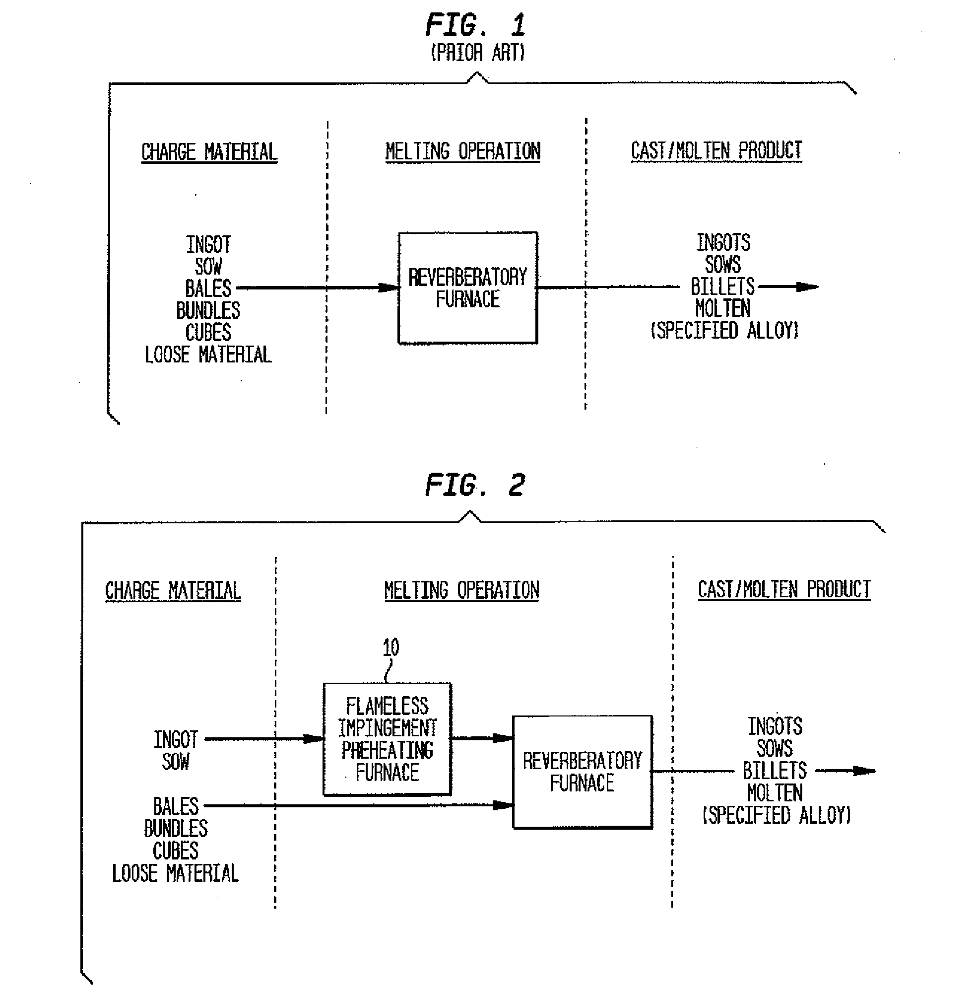
[0015]Referring to FIG. 2, the preheater furnace embodiment of the present invention shown generally at 10 is added to or used in conjunction with a known melter. The preheater 10, when combined with a conventional melting furnace, provides production flexibility in terms of a) the ability / option to heat the scrap in the preheater rather than in the melting furnace, and b) the ability to heat charge material in the preheater while at the same time heating material in the conventional melting furnace, thereby increasing the production capacity of the facility (in other words, expanding the operating window).

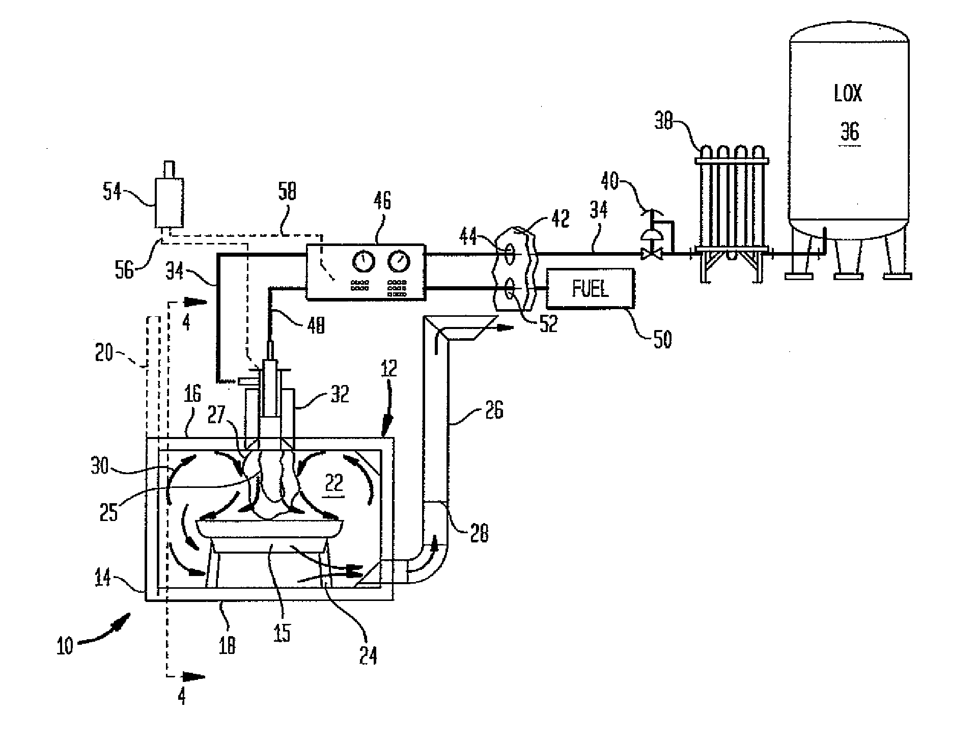
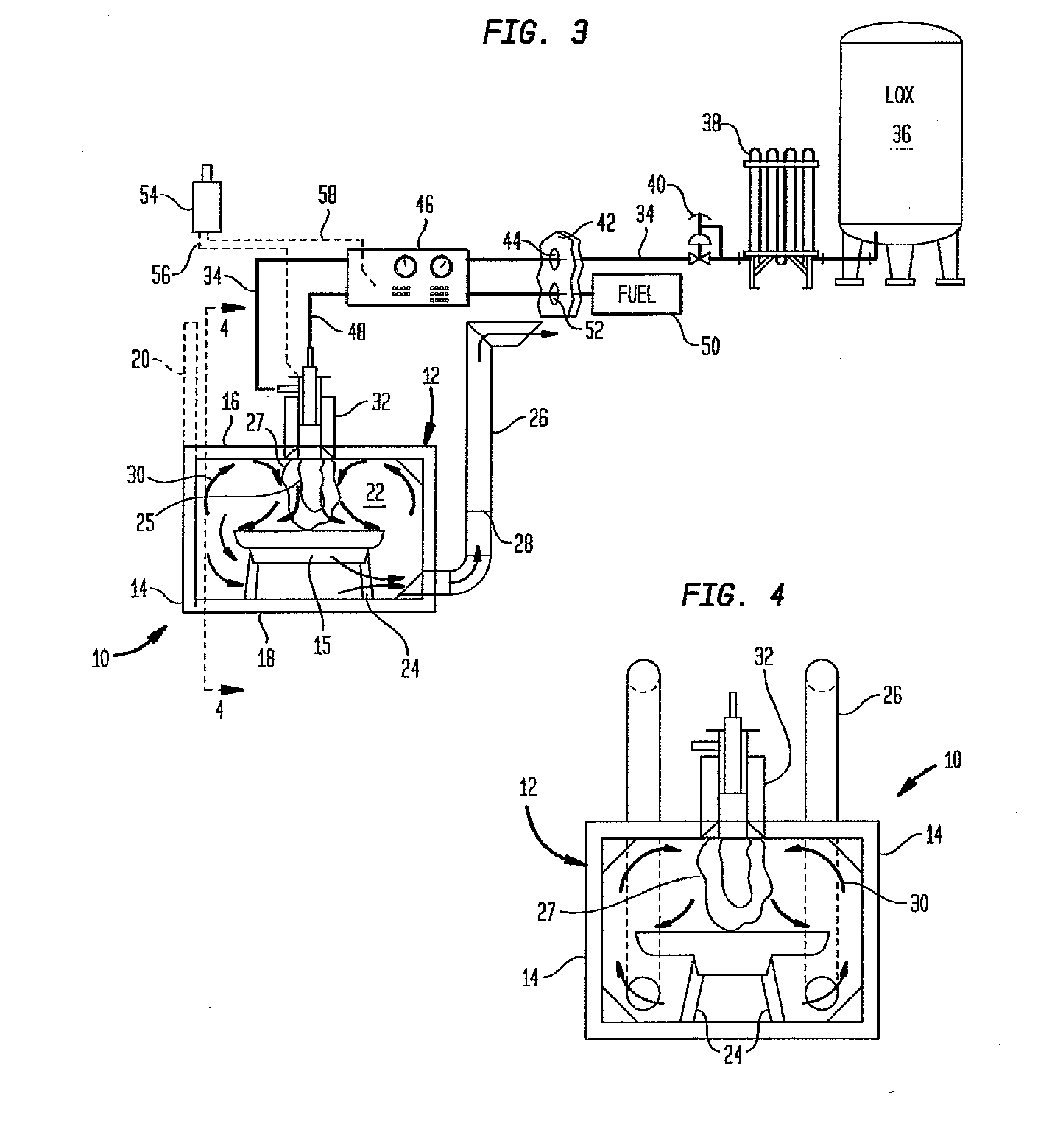
[0016]Now referring to FIGS. 3 and 4, the preheater furnace embodiment 10 is shown for use with conventional melting furnaces (not shown). The preheater 10 includes a housing 12 which may have a plurality of side walls 14 depending upon the shape of the housing 12. A top 16 or crown and a bottom 18 or floor is provided for the housing 12. One of the side walls 12 is provided with ...


PUM


Abstract

A heating apparatus for charge material includes a preheater having a housing with a combustion chamber therein constructed and arranged to receive the charge material, at least one oxy-fuel burner mounted to the housing for providing a combustion flame to the combustion chamber wherein a combustion atmosphere is created to provide heat sufficient to increase a temperature of the charge material, a fuel supply and an oxidant supply connected to the at least one oxy-fuel burner, an exhaust in communication with the combustion chamber for removing a portion of the combustion atmosphere from the combustion chamber; and a melter separate from the preheater for coaction therewith to receive the heated charge material for being melted in the melter.

Description

[0001]The present embodiments relate to apparatus and methods for preheating charge materials to be subjected to a heating or melting operation.[0002]In a melting or reheating furnace, a lower and more uniform flame temperature will reduce the likelihood of overheating the charge material, reduce the formation of oxides of nitrogen (NOx) and the formation of metal oxides (scale or dross), increase furnace throughout, and reduce furnace fuel consumption, due to an improved heat transfer mechanism.[0003]Fossil fuel melting furnaces for aluminum and copper utilize energy released from a flame to raise the temperature of the charge material and the furnace superstructure (which consists of a refractory lining and steel structure). Air-fuel fired furnaces are fairly inefficient, with only about 20-30% of the gross energy released going to the charge material during the melt portion of the furnace cycle. The remainder of the gross energy is used to heat the superstructure, or lost through...

Claims


Application Information

Patent Timeline
Patent Type & Authority Applications(United States)
IPC IPC(8): F27D7/00
CPCF27D7/00F27D13/00
Inventor MORAN, CHRISTOPHER
Owner LINDE AG
Why Eureka
Try Eureka