Magnetic circuit for sputtering apparatus

a sputtering apparatus and magnetic circuit technology, applied in the direction of magnets, magnets, vacuum evaporation coatings, etc., can solve the problems of plasma density decline, electrical discharge instability, and the strength of the magnetic field to be produced, so as to improve demagnetization resistance, improve demagnetization resistance, and increase the magnetic field strength. effect of arc-shaped magnetic field lines

Inactive Publication Date: 2012-05-10
SHIN ETSU CHEM IND CO LTD
View PDF3 Cites 6 Cited by
  • Summary
  • Abstract
  • Description
  • Claims
  • Application Information

AI Technical Summary

Benefits of technology

[0009]In view of the above, an object of the present invention is to provide a magnetic circuit for a magnetron sputtering apparatus, which produces arc-shaped magnetic field lines of greater magnetic field strength, and has an improved demagnetization resistance.
[0010]In order to achieve the above object, the inventor has found and taken an advantage of the fact that the strength of the magnetic field represented by the arc-shaped magnetic field lines can be increased while preventing the demagnetization of a horizontally magnetized magnet, by using the horizontally magnetized magnet formed of a magnet which is subjected to a diffusion treatment of Dy or Tb from a target-facing surface of the horizontally magnetized magnet so that the magnetic coercive force of a target side region of the horizontally magnetized magnet becomes greater in value than the magnetic coercive force of the center of the horizontally magnetized magnet. Specifically, the inventor has devised a magnetic circuit for a magnetron sputtering apparatus, comprising: an inner magnet having a magnetization direction perpendicular to a surface of a target; an outer magnet disposed around the inner magnet and having a magnetization direction opposite to that of the inner magnet; and a horizontally magnetized magnet disposed between the inner magnet and the outer magnet and having a magnetization direction perpendicular to those of the inner magnet and the outer magnet, in which the horizontally magnetized magnet is formed of a magnet which is subjected to a diffusion treatment of Dy or Tb from a target-facing surface of the horizontally magnetized magnet so that the magnetic coercive force of a target side region of the horizontally magnetized magnet becomes greater in value than the magnetic coercive force of the center of the interior of the horizontally magnetized magnet.
[0011]According to one aspect of the present invention, since the horizontally magnetized magnet formed of a permanent magnet, which has a high residual magnetization and in which the target side region has a greater magnetic coercive force than the center of the interior is used in the magnetic circuit for the magnetron spattering apparatus, the magnetic circuit can produce an arc-shaped magnetic field line having a greater magnetic field strength than that of conventional circuit. Accordingly, a greater plasma density can be obtained at a low pressure, and the directivity of target particles can be improved. Therefore, it is possible to provide a sputtering apparatus which enables the film deposition for a finer wiring structure. Further, since the enhancement of the arc-shaped magnetic field line enables to obtain a sufficient magnetic field strength over target's surface, it is possible to increase the target thickness, and accordingly the production life of the target can be extended. Furthermore, since one surface of the horizontally magnetized magnet may be treated to increase the magnetic coercive force thereof, there may be no need of applying a diffusion treatment to all the surfaces of magnet. It is possible to mass-produce horizontally magnetized magnets with enhanced magnetic coercive force, and to improve the film depositing performance of a sputtering apparatus with an additional simple process, by assembling multiple horizontally magnetized magnets and by treating only one surface thereof in one operation to diffuse Dy or Tb from the surface.

Problems solved by technology

However, the decreased ambient pressure will lead to a decline of plasma density, and thereby electrical discharge might become unstable.
Therefore, using a magnet having an excessively high magnetic coercive force might lead to a decline of the strength of the magnetic field to be produced.

Method used


Image

  • Magnetic circuit for sputtering apparatus
  • Magnetic circuit for sputtering apparatus
  • Magnetic circuit for sputtering apparatus

Examples


example 1

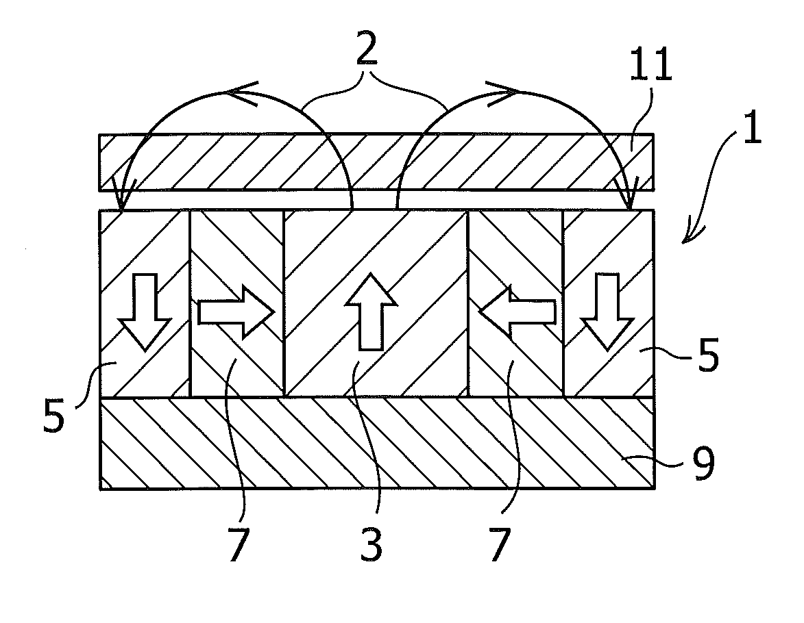
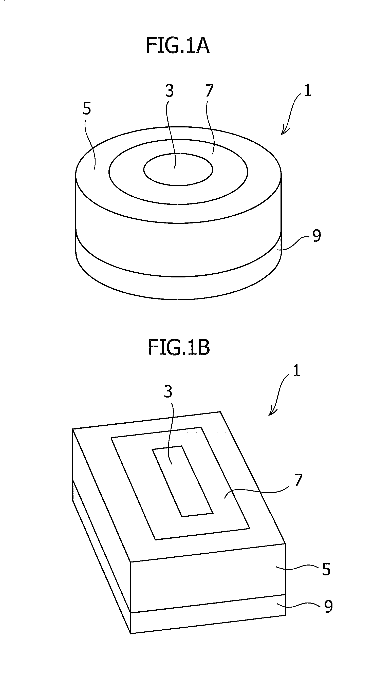
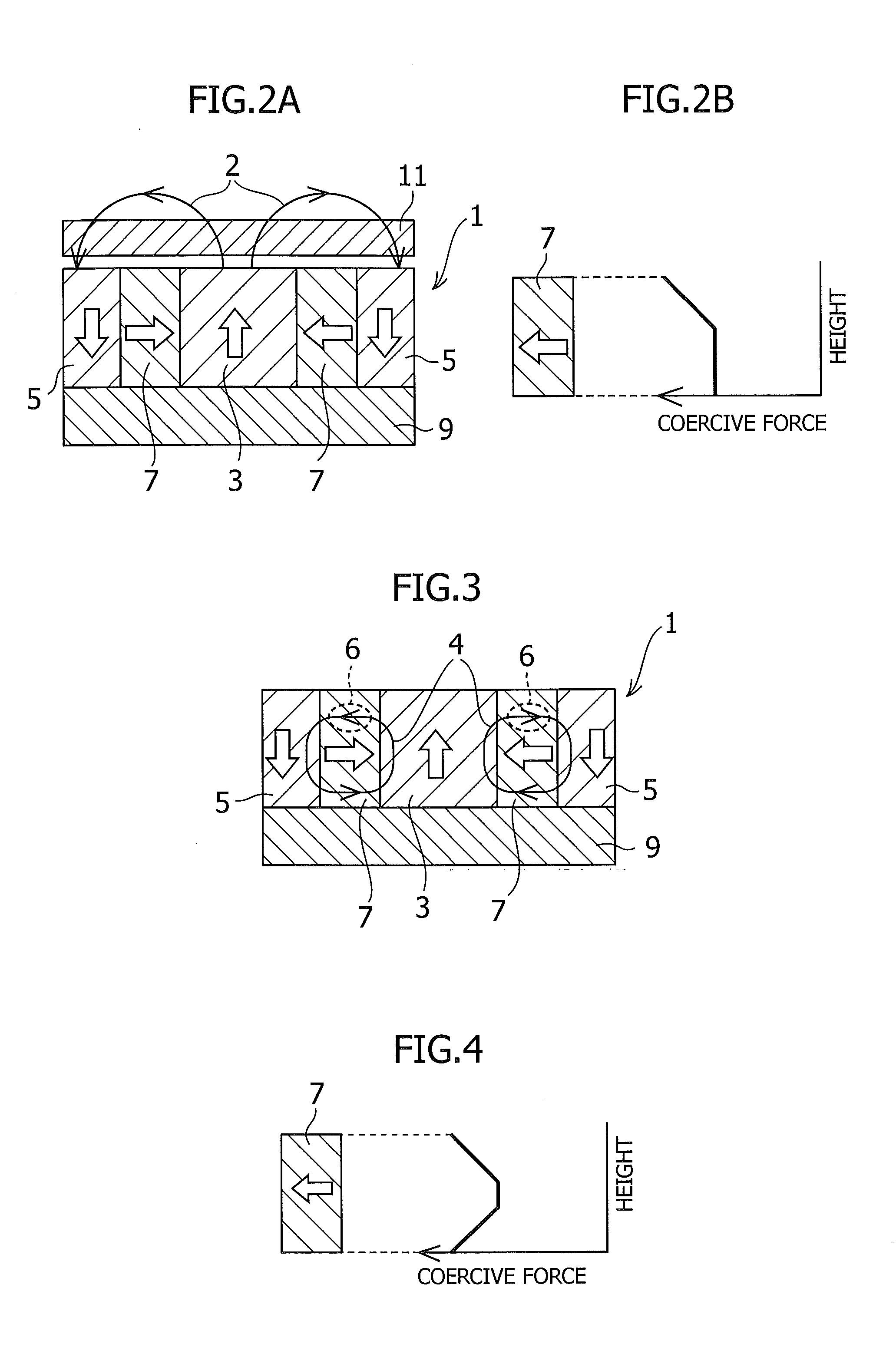
[0034]As an inner magnet, provided was a cylindrical magnet having dimensions of a diameter of 40 mm and a height of 30 mm and being magnetized in height direction, formed of a sintered NdFeB magnet having a residual magnetization of 1.42 T and a magnetic coercive force of 900 kA / m. As an outer magnet, provided were twelve concentric arc-shaped magnets having the same magnetic properties and having dimensions of an outer diameter of 120 mm, an inner diameter of 80 mm, a circular arc angle of 30 degrees, and a height of 30 mm and being magnetized in its height direction. As a horizontally magnetized magnet, provided were twelve concentric arc-shaped magnets having the same magnetic properties and having dimensions of an outer diameter of 80 mm, an inner diameter of 40 mm, a circular arc angle of 30 degrees, and a height of 30 mm and being magnetized in a direction toward the center of the circular arc. Only the horizontally magnetized magnet was subjected to a diffusion treatment. Th...


PUM

PropertyMeasurementUnit
heightaaaaaaaaaa
magnetic heightaaaaaaaaaa
heightaaaaaaaaaa

Abstract

The present invention provides a magnetic circuit for a magnetron sputtering apparatus, which produces arc-shaped magnetic field lines of high magnetic field strength over a target surface, and has an improved demagnetization resistance. The magnetic circuit includes: an inner magnet; an outer magnet having a magnetization direction opposite to that of the inner magnet, and surrounding the inner magnet; a horizontally magnetized magnet disposed between the inner and outer magnets, and magnetized in a direction perpendicular to those of the inner and outer magnets, and in a direction from the inner magnet to the outer magnet, or from the outer magnet to the inner magnet; and a yoke configured so that a magnetic flux passes through the yoke between the inner and outer magnets, in which a magnetic coercive force of the horizontally magnetized magnet is greater in a region closer to the target side than in a center of the magnet interior.

Description

CROSS-RELATED APPLICATIONS[0001]This application claims priority from Japanese Patent Application No. 2010-248474; filed Nov. 5, 2010, the disclosure of which is incorporated herein by reference in its entirety.BACKGROUND OF THE INVENTION[0002]The present invention relates to a magnetron sputtering apparatus which is used for forming of a wiring layer of a semiconductor device, manufacturing of hard disk recording media, and the like, and relates to a magnetic circuit for the magnetron sputtering apparatus which circuit applies a magnetic field to a target.[0003]Magnetron sputtering apparatuses are widely used in a film depositing technique for materials of electric and electronic components. In such a magnetron sputtering apparatus, a target material or target 101 is placed facing a substrate 110 which is placed in a vacuum chamber, and a magnetic circuit 50 is disposed in a back side of the target so as to provide an arc-shaped magnetic field represented by arc-shaped magnetic fie...

Claims


Application Information

Patent Timeline
Patent Type & Authority Applications(United States)
IPC IPC(8): C23C14/35H01F7/02
CPCH01J37/3405H01F41/0293H01J37/3461H01J37/3452H01L21/203
Inventor KOBAYASHI, HIDEKI
Owner SHIN ETSU CHEM IND CO LTD
Why Eureka
Try Eureka