

Mass spectrometer and mass spectrometry method
a mass spectrometer and mass spectrometry technology, applied in mass spectrometers, separation of dispersed particles, separation processes, etc., can solve the problem of low duty cycle and achieve the effect of high duty cycl
- Summary
- Abstract
- Description
- Claims
- Application Information
AI Technical Summary
Benefits of technology
Problems solved by technology
Method used
Image

Examples
embodiment 1
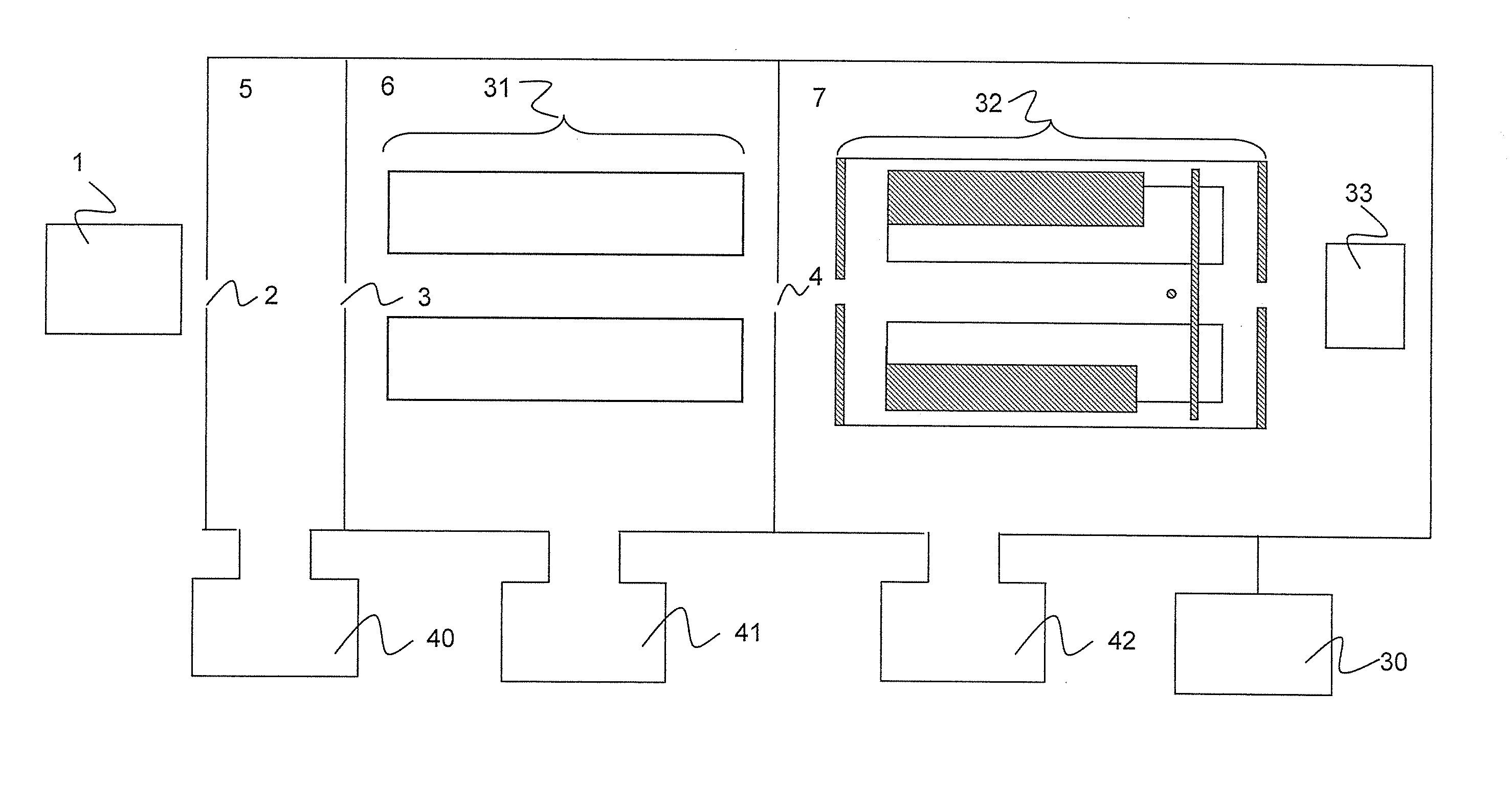
[0033]FIG. 1 is a configuration diagram showing one embodiment of a mass spectrometer of the present invention. Note that a mechanism of introducing a buffer gas and the like is omitted for simplicity. Ions generated by an ion source 1, such as an electrospray ion source, an atmospheric pressure chemical ion source, an atmospheric pressure photoion source, an atmospheric pressure matrix-assisted laser desorption ion source, or a matrix-assisted laser desorption ion source, are introduced into a first differential exhaust unit 5 through a first orifice 2. The ion source such as the electrospray ion source, the atmospheric pressure chemical ion source or the atmospheric pressure photoion ion source can generate ions in both the polarities at the same time by using two whiskers. Specifically, a positive high voltage of 500 V to 8000 V is applied to one of the whiskers, and a negative high voltage of 500 V to 8000 V is applied to the other. The first differential exhaust unit 5 is evacu...
embodiment 2
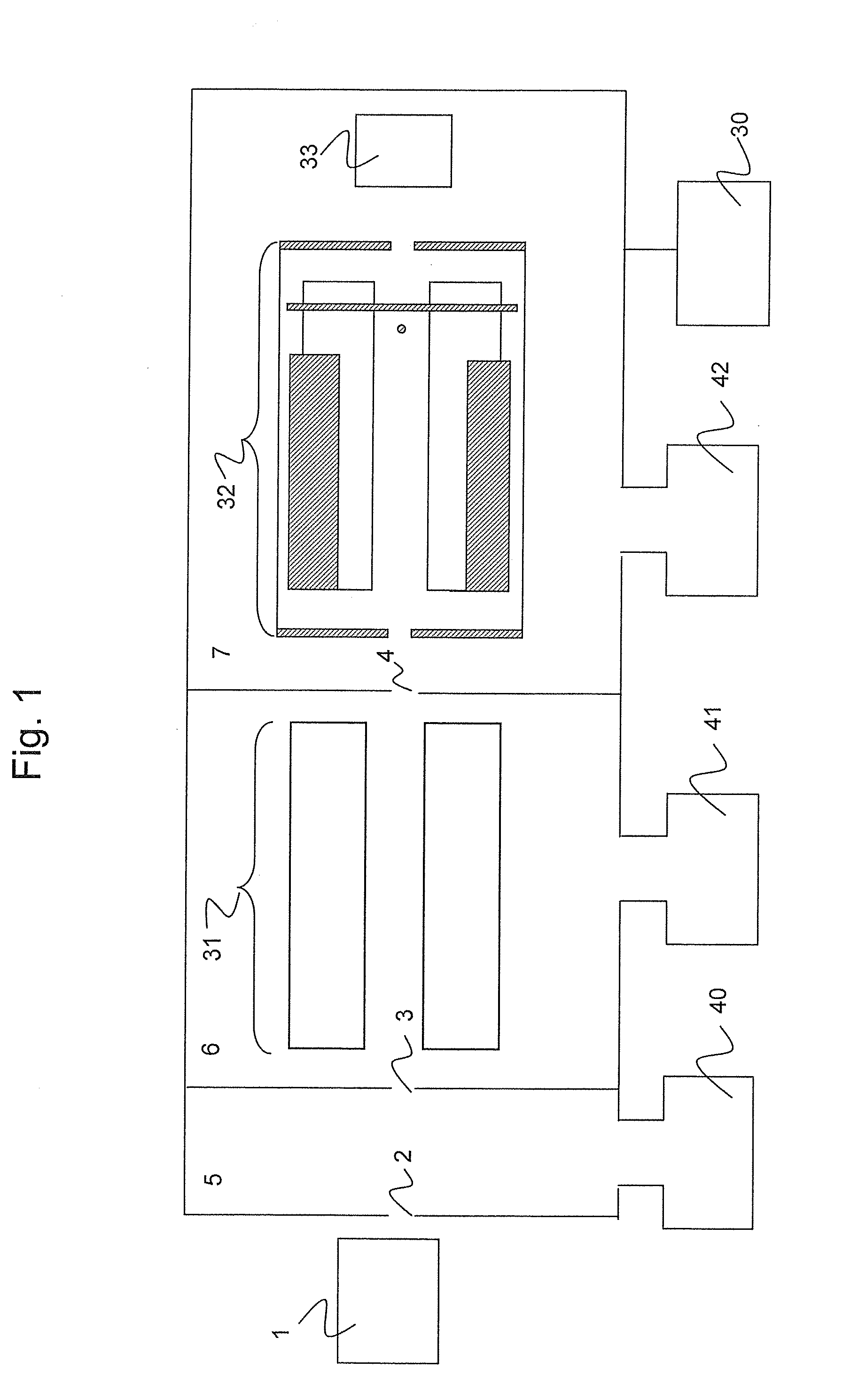
[0048]FIG. 6 shows an apparatus configuration in Embodiment 2. The ion trap part 32 is arranged in the high-vacuum chamber 7 and is maintained at 0.1 mTorr to 10 mTorr. The exit-end electrode 4 of the ion guide part also serves as the entrance-end electrode of the ion trap in this configuration, but a configuration of other components is the same as that in Embodiment 1. FIG. 7 shows measurement sequences. The voltage application from the ion source to the ion guide part 31 is the same as in Embodiment 1. When the offset potential of the quadrupole rod electrodes of the ion trap part 32 is changed, voltages of the other electrodes of the ion trap part 32 are controlled in conjunction with the voltages so that potential differences from the offset potentials of the quadrupole rod electrodes 20 can be the same as the applied voltages in Embodiment 1. Hereinbelow, a description is given of voltage application to the electrodes at the time of the cation measurement. At the time of the a...
embodiment 3
[0050]Embodiment 3 shows an example of a sequence operation in a case of using the same apparatus as in Embodiment 2. FIG. 8 shows measurement sequences. Control sequences for the components except the exit-end electrode 4 of the ion guide part are the same as in Embodiment 1.
[0051]When an alternating voltage of 100 kHz to 4 MHz is applied to the exit-end electrode 4 of the ion guide part, a pseudo-potential expressed with (Formula 4) is formed near the exit-end electrode.
ψ=e4mΩ2E2_[Formula4]
[0052]Herein, e denotes an electric quanta; m, an m / z of ions; Ω, a frequency of the alternating voltage; Ē, an electric field averaged in time.
[0053]In a mass scanning step, a releasing step, and a cooling step, the magnitude of the pseudo-potential of the exit-end electrode 4 is set to be higher than an offset potential of the ion guide part 31, so that ions introduced into the ion guide part 31 from the ion source 1 are trapped in the ion guide part 31. In an accumulating step, the magnitude ...
PUM
 Abstract
Description
Claims
Application Information