Transceiver apparatus, system and methodology for superior In-Vivo imaging of human anatomy

Active Publication Date: 2012-05-10
HETHERINGTON HOBY P +2
View PDF20 Cites 56 Cited by
  • Summary
  • Abstract
  • Description
  • Claims
  • Application Information

AI Technical Summary

Benefits of technology

[0025](iii) the juncture of the pre-shaped housing segments conforms the interior surface geometry of the structured housing to a limited gap distance from the surface of the contained part of the subject's body and concomitantly controls the void volume of the cavity space (and that fraction of the interior volume which is

Problems solved by technology

Nevertheless, despite the recent developments in transceiver designs, there remains the long recognized difficulties and presently continuing problems concerning: (1) The sensitivity of different RF coil structures to changes in human sizes, shapes, and dielectric properties; (2) the present lack of control regarding transceiver performance characteristics (such as B1 field homogeneity and amount of power deposited into the tissue as reflected by the specific absorption rate or SAR); and (3) the need for repeated adjustments to an RF coil to accommodate different persons in the clinical MRI environment.
As merely one illustrative example, despite the availability of 7 T systems dating from late 1990s, their use in clinical applications of the human brain has been slowed by technical hurdles associated with detector design.
This limitation is primarily due to drastically increased B1 inhomogeneity for conventional head-sized volume coils [see Vaughan, J. T., et al., 7 T vs.
Another critical factor limiting progress at high magnetic field strength is the efficiency of transmission and the limitations that such a field imposes on excitation and refocusing bandwidth, and on power deposition.
However, the differences in he

Method used


Image

  • Transceiver apparatus, system and methodology for superior In-Vivo imaging of human anatomy
  • Transceiver apparatus, system and methodology for superior In-Vivo imaging of human anatomy
  • Transceiver apparatus, system and methodology for superior In-Vivo imaging of human anatomy

Examples


Embodiment Construction

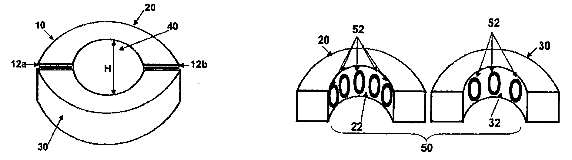
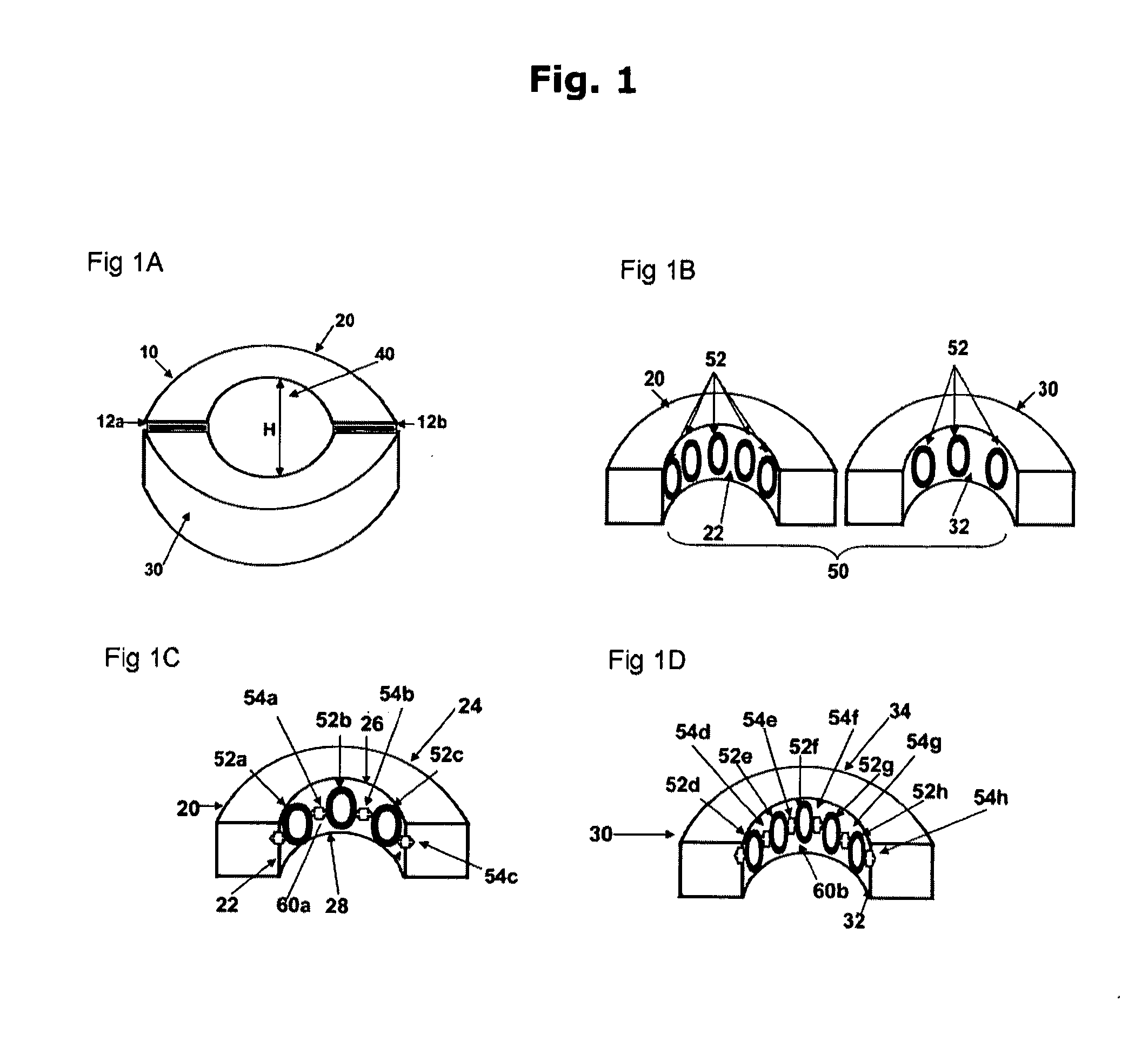
[0087]The present invention provides an improved transceiver apparatus capable of transmitting RF pulses and receiving RF signals at specified frequencies; and which functions to provide superior in-vivo spectroscopy or imaging of a particular portion or all of the anatomic systems, organs and tissues then existing within the body of a living subject. The structure and design of the improved transceiver apparatus is a unique achievement and represents an unpredicted advancement in this technical field.

[0088]Accordingly, the breadth and scope of the present invention includes a system of enhanced capabilities in which the improved transceiver apparatus is used as an essential component in a computer controlled disposition. Moreover, the methods of the invention are suitable for use in three different clinical procedures: magnetic resonance imaging (“MRI”); nuclear magnetic resonance spectroscopy (“MRS”); and nuclear magnetic resonance spectroscopic imaging (“MRSI”). Each of these thr...


PUM


Abstract

The inventive subject matter as a whole is an improved transceiver apparatus and system for diagnostic evaluations of living subject, human or animal; and is particularly effective as a clinical tool for the spectroscopic scanning or magnetic resonance imaging of humans suspected of being afflicted with a particular disease, disorder, or pathology. The improved transceiver apparatus is used as an essential component in a computer controlled system suitable for magnetic resonance imaging (“MRI”), or nuclear magnetic resonance spectroscopy (“MRS”), and/or nuclear magnetic resonance spectroscopic imaging (“MRSI”); and the present improvement of these electromagnetic signaling systems will provide far more accurate and precise visual images and accumulated data for the clinician or surgeon, as well as serve as a basis upon which to make a diagnosis and decide upon a mode of therapeutic treatment for that individual.

Description

PRIORITY CLAIM[0001]The present invention was first submitted as U.S. Provisional Patent application Ser. No. 61 / 164,096 filed on Mar. 27, 2009 and as U.S. Provisional Patent Application Ser. No. 61 / 164,054 filed on Mar. 27, 2009. The legal priority and effect of these first filings are expressly claimed herein.FIELD OF THE INVENTION[0002]The present invention is concerned with improvements to the equipment and procedures used today for performing nuclear magnetic resonance imaging (“MRI”), nuclear magnetic resonance spectroscopy (“MRS”), and nuclear magnetic resonance spectroscopy imaging (“MRSI”); and is directed to an improved transceiver apparatus which can provide more accurate and precise, high resolution visualizations and images of particular anatomic systems, organs and tissues existing within the body of a living subject.BACKGROUND OF THE INVENTIONMagnetic Resonance Imaging (MRI)[0003]MRI has proven to be a valuable clinical diagnostic tool for examination of a wide range ...

Claims


Application Information

Patent Timeline
IPC IPC(8): G01R33/44
CPCG01R33/34007G01R33/34076G01R33/34084G01R33/341G01R33/5659G01R33/3453G01R33/3635G01R33/365G01R33/3685G01R33/3415
Inventor HETHERINGTON, HOBY P.PAN, JULLIE W.AVDIEVICH, NIKOLAI I.
Owner HETHERINGTON HOBY P
Why Eureka
Try Eureka