
Heater design for heat-trimmed thin film resistors

a thin film resistor and heat-trimmed technology, applied in resistors, non-adjustable resistors, coatings, etc., can solve problems such as changing the resistance of resistors

Active Publication Date: 2012-05-17
STMICROELECTRONICS PTE LTD
View PDF5 Cites 18 Cited by
  • Summary
  • Abstract
  • Description
  • Claims
  • Application Information

AI Technical Summary

Benefits of technology

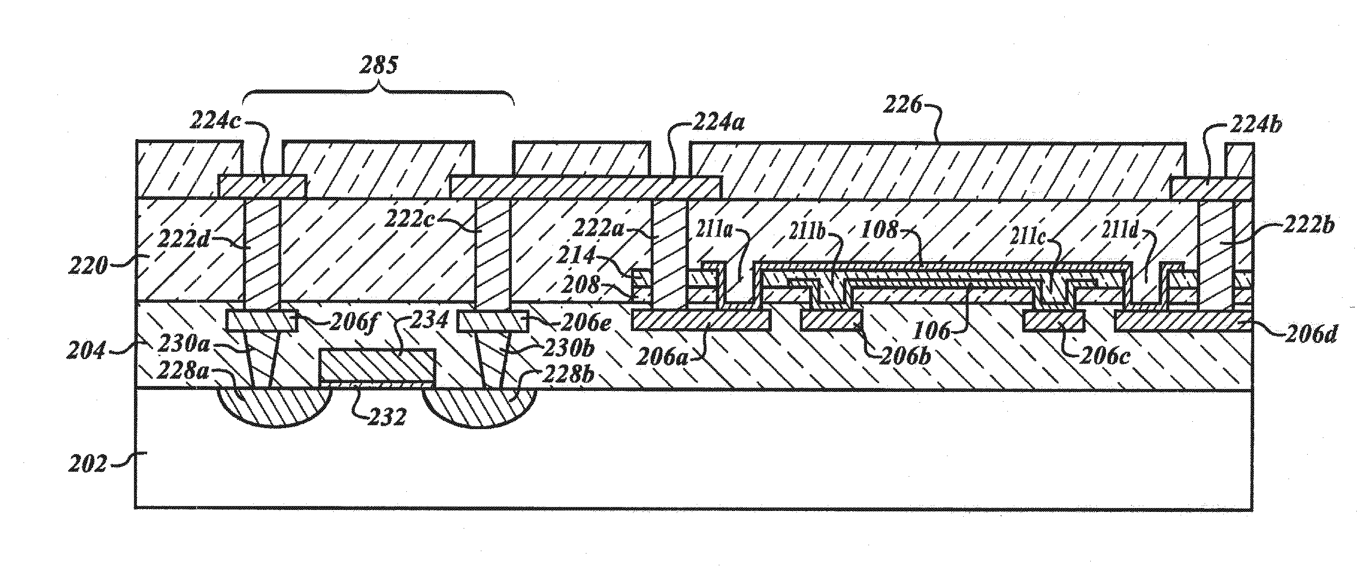
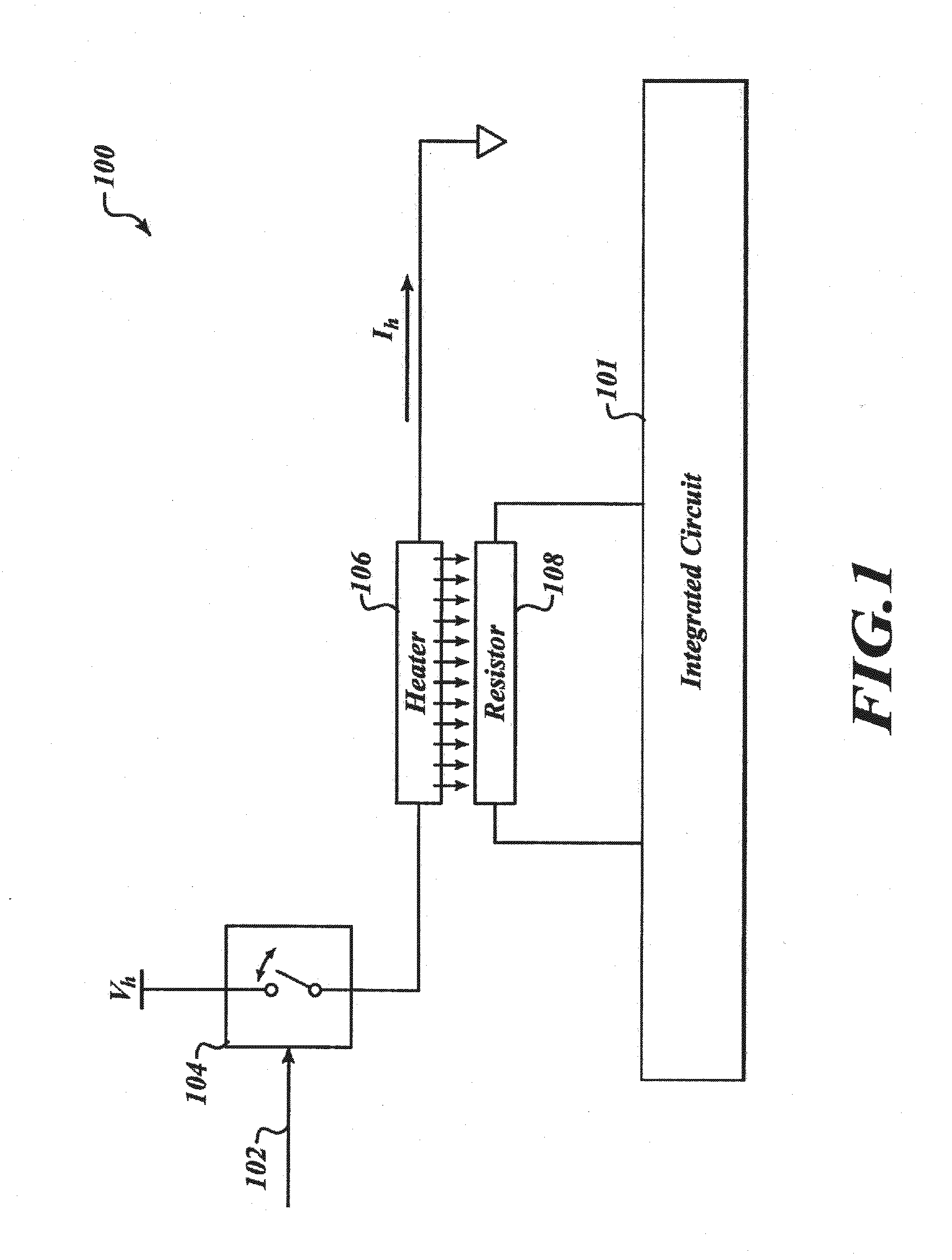
[0007]According to one embodiment, a heat-trimmable resistor comprises a thin-film resistive element configured as a resistor that is connected to or connectable to a circuit. The heat-trimmable resistor further comprises a thin-film heating region proximal at least a portion of the thin-film resistive element, and an electrically-conductive material disposed in electrical contact with the thin-film heating region and having a lower sheet resistance than the thin-film heating region. The thin-film heating region may define an active area of the heat-trimmable resistor, and substantially cover a portion or substantially all of the thin-film resistive element. The electrically-conductive material may provide an electrical connection between the thin-film heating region and a conductive interconnect, and may reduce heat generation in non-active areas of the heat-trimmable resistor.
[0008]In one embodiment, the heat-trimmable resistor is connected to an amplifier in a feedback configuration that will affect the gain. The gain of an operational amplifier (“op amp”) circuit can be controlled by the value of a feedback resistor. If a precise gain is needed by the circuit, the feedback resistor can be precisely tuned to achieve a desired op amp performance.
[0009]In another embodiment, the resistor is trimmed and used in a current sense configuration. In a current sense configuration, a resistor may be placed across the input terminals of an op amp. The op amp is used to sense and amplify the voltage drop across the resistor. Knowing the exact resistance of the resistor and the gain of the op amp will allow one to determine the amount of current flowing through the resistor for evaluating the parameter of interest. The value of the resistor can be more precisely set than just using standard process manufacturing techniques. The value of the resistance of the resistor will affect the range of currents detectable by the current sense configuration. For some sense circuits, a very low resistor may be preferred, while in other types of sense circuitry a higher resistance will provide more accurate sensing and better circuit performance. Thus, the ability to adjust the resistor may improve the effectiveness of a current sense circuit.
[0016]Alternatively, the purchaser of the chip may also trim the resistor just prior to using it in an end circuit. The user, upon purchase of the chip in its complete package form, may perform various tests on the integrated circuit package according to their desired end use of the completed circuit. The user can determine what resistance value is preferred and, by applying appropriate voltage to the terminals of the package, heat the resistor to the selected value and thus change the resistor to have a value which provides the preferred circuit performance.

Problems solved by technology

Separating the heater from the resistor by one or more thermal separators and applying a voltage to the heater results in changing the resistance of the resistor.

Method used


Image

  • Heater design for heat-trimmed thin film resistors
  • Heater design for heat-trimmed thin film resistors
  • Heater design for heat-trimmed thin film resistors

Examples


examples

[0143]Several experiments were carried out to investigate effects of heater design variations on heating efficiency and performance of a heat-trimmable, thin-film resistor. In the experiments, three designs were trialed. The designs tested are depicted in FIGS. 26A-26C. The first design, depicted in FIG. 26A, included a leg of electrically conductive material 605 that provided current to distributed heater 620. The electrically-conductive material 605 had significantly lower sheet resistance than that of the heater. The heater comprised an active region 640 patterned to have a plurality of straight legs of length L and width W. The active area was configured to be in close proximity to an underlying resistive element (not shown). There were significant portions of the heater that did not overly the resistive element and were of the same material and thickness as the active region. Connection between the heater 620 and conductive material 605 was established through a plurality of vi...


PUM


Abstract

A heater design for post-process trimming of thin-film transistors is described. The heater incorporates low sheet-resistance material deposited in non-active connecting regions of the heater to reduce heat generation and power consumption in areas distant from active heating members of the heater. The heating members are proximal to a thin-film resistor. The resistance of the thin-film resistor can be trimmed permanently to a desired value by applying short current pulses to the heater. Optimization of a heater design is described. Trimming currents can be as low as 20 mA.

Description

CROSS-REFERENCE TO RELATED U.S. APPLICATIONS[0001]The present application is a continuation in part of U.S. patent application Ser. No. 12 / 562,026 filed on Sep. 17, 2009, which claims priority to U.S. provisional patent application No. 61 / 097,805 filed on Sep. 17, 2008, both of which are incorporated herein by reference.BACKGROUND[0002]1. Technical Field[0003]This description generally relates to the field of resistance trimming.[0004]2. Background[0005]Traditional methods of trimming resistors which are embedded within integrated circuits are limited to pre-assembly stages of manufacturing or require forfeiture of significant silicon real estate to obtain precision trims. One method includes using a laser to cut away portions of the resistor to alter its resistance. This method requires access to the fabrication layer in which the resistor is deposited. Additionally, this method cannot be accomplished during the application of the device containing the resistor. Another method incl...

Claims


Application Information

Patent Timeline
IPC IPC(8): H01C10/00H01C17/075
CPCH01C17/265H01C17/267H01L2924/13033H01L2924/1461H01L2924/1301H01L2924/1305H01L2924/13091H01L23/345H01L23/5228H01L24/05H01L27/016H01L27/0688H01L28/20H01L2924/01019H01L2924/00H01L2924/14
Inventor LEUNG, CALVINLE NEEL, OLIVIER
Owner STMICROELECTRONICS PTE LTD
Learn More