Optical micro-projection system and projection method

a technology of optical microprojection and projection method, which is applied in the direction of optical elements, instruments, and reradiation using refraction, etc., can solve the problems of human eye safety, no of the existing techniques are completely efficient, and damage to any of the parts

Inactive Publication Date: 2012-05-17
GOOGLE LLC
View PDF13 Cites 61 Cited by
  • Summary
  • Abstract
  • Description
  • Claims
  • Application Information

AI Technical Summary

Benefits of technology

[0022]It is therefore an object of the present invention to provide a method and a device providing protection for human and animal bodies, and more particularly eye protection for humans during use of a laser projection system.

Problems solved by technology

The damage to any of the parts occurs when the light is absorbed by the parts.
With the growing demand for laser diode for various applications such as telecom and laser pointer device, the eye safety issue for human became an issue and was mainly handled by different methods.
A problem of these laser safety techniques, for the specific laser projection application, is that none of these existing techniques are completely efficient, as the existing solutions do not prevent eye damage if the user switches on the projector while he looks directly toward the light source and while not moving.
Moreover, most of these techniques are complex and expensive.
Another problem of the existing techniques to prevent eye damage is that the use of a CCD detector or capacitive detection do not allow having a directional sensing and is typically much larger that the field of projection of moving object.
For hand-held application of laser projector, this working behaviour, even though allowing eye safety apparatus is therefore not adapted to normal operation and use.
A further problem of the eye safety technique while using laser source, is that the use of a CCD detector or an external motion sensor further increase the complexity of the overall laser-based projection system by adding a different technology to the technology initially used for the projection purpose.
However, in existing projection systems, there is no complete safety system that can avoid eye damage when the eye is within the field of projection above the MPE limit, as presented in FIG. 3.
However, these devices are of no use to provide micro-projection system or methods.
Moreover, the correction depends on the image taken by an additional camera or device which is not perfectly aligned with the projection system, which adds to the cost and complexity, and creates parallax errors.
This device is of no use for eye-safety.
Distance data involve only few points, therefore limiting accuracy and potential other uses of the data.
Again, the distance measuring system is not aligned with the projection system, creating parallax errors.

Method used


Image

  • Optical micro-projection system and projection method
  • Optical micro-projection system and projection method
  • Optical micro-projection system and projection method

Examples


Embodiment Construction

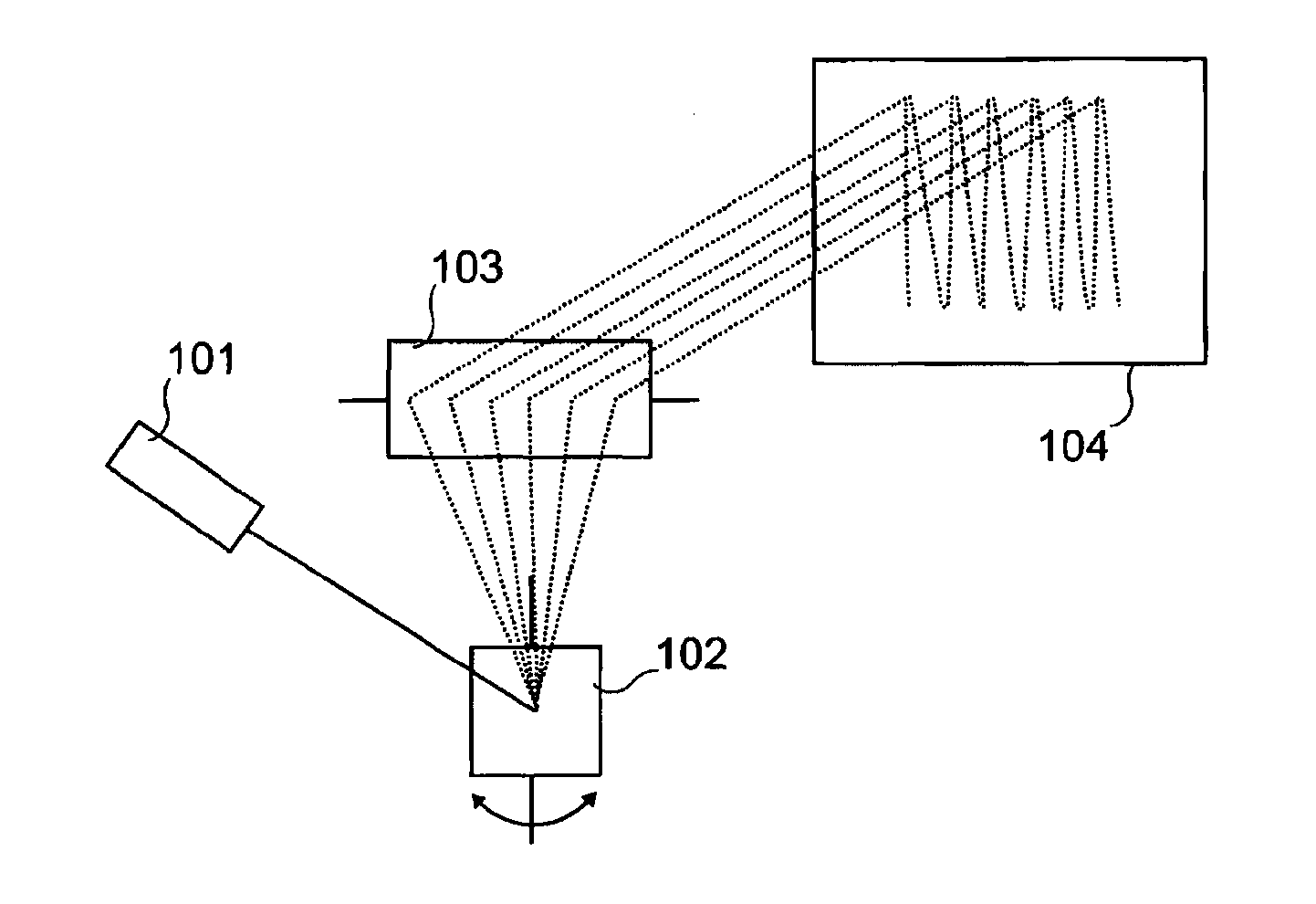
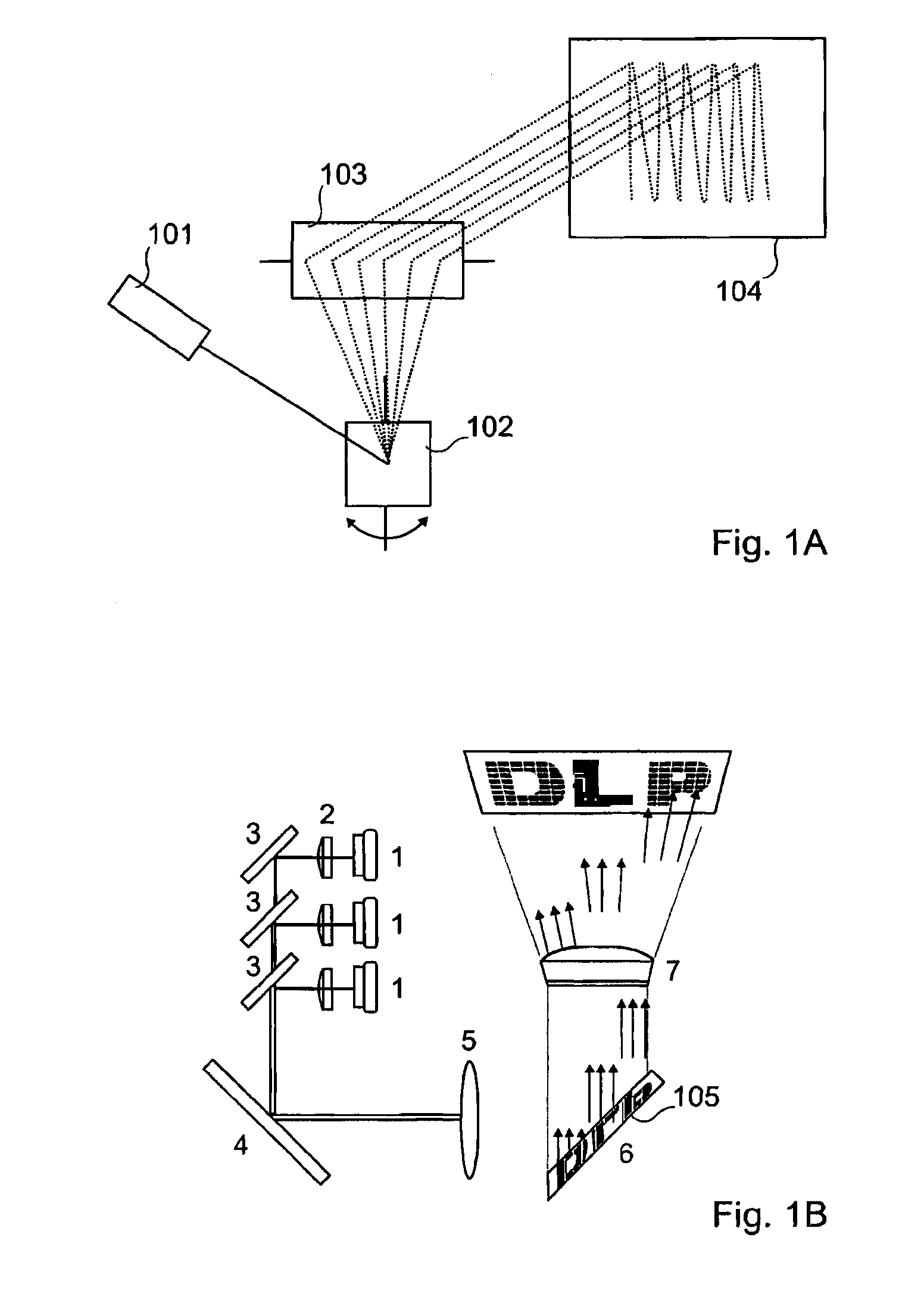
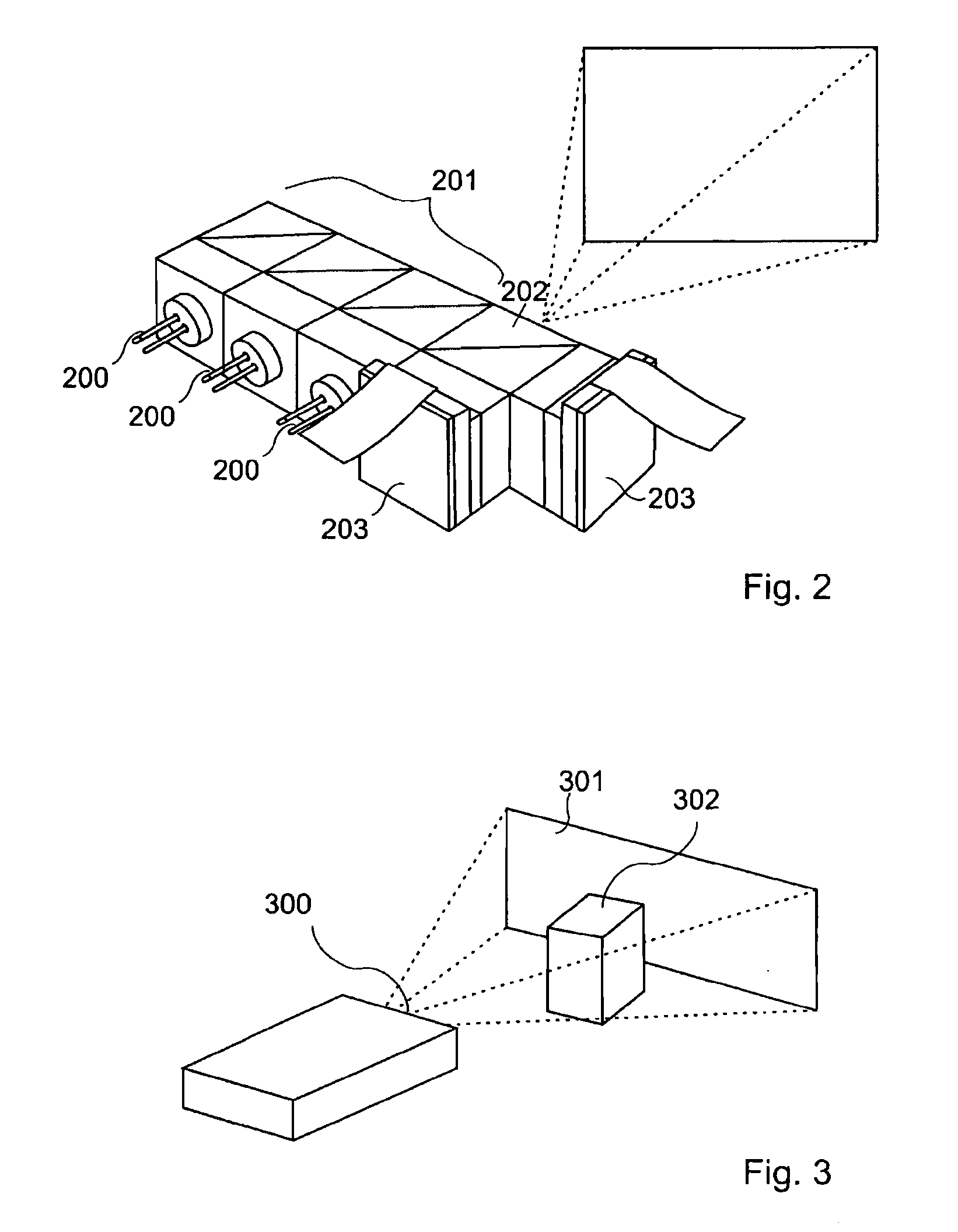
[0096]For clarity, as is generally the case in representation of microsystems, the various figures are not drawn to scale.

[0097]Laser diodes are made of two discrete components, a laser diode “LD”400 and a photodiode “PD”401, as presented in FIG. 4, the first component is used to generate the laser light while the second is used to monitor the light emission power of the laser diode. For many applications the laser diode and the photodiode are feedback looped to maintain the optical output power of the laser diode constant, independently of the working temperature.

[0098]A laser diode remote sensing technique described by Thierry Bosch in “An overview of self-mixing sensing applications” can be used to measure displacement, vibration, velocity and distance by using the Optical Feedback Interferometry (OFI) properties inside the active cavity of the laser diode 600 (see FIG. 5).

[0099]FIG. 5A presents the Self-Mixing “SM” technique that consists in injecting a triangular waveform modul...


PUM


Abstract

An optical micro-projection system comprising the following components: at least one laser light source (200, 400, 402, 600); at least one movable mirror (102, 103, 203) for deviating light from said light source to allow generation of images on a projection surface (104, 301, 303, 306, 603); a self mixing module for measurement of the distance (604) between the projection source and a projection surface, said self mixing module comprising:—at least one photodiode (401, 601) for monitoring the light emission power of the laser light source;—an optical power variation counter for counting optical power variations (605); successive displacements of said mirror allowing the self mixing module providing successive projection distance measurements of a plurality of points of said projection surface. A projection method for optical micro-projection system and a distance measurement method are also provided.

Description

FIELD OF THE INVENTION[0001]The present invention relates to an optical micro-projection system comprising at least one laser light source and at least one movable mirror, preferably of MEMS type. It also relates to a projection method and a projection distance measurement method.BACKGROUND OF THE INVENTION[0002]The biological effects of electromagnetic radiation to human beings can be divided into two categories, ionizing and non-ionizing radiation. The first, ionizing radiation, is related to cosmic and x-ray wavelengths and to nuclear radiation. The second, non-ionizing radiation is related to ultraviolet, visible, infrared, microwave, and radio wavelengths. Image and video projection devices works within the visible spectrum of the light, therefore, non-ionizing hazard has to be investigated and avoided while running the device.[0003]Biological effects of non-ionizing radiation are dependent on the spectral region of the radiation (wavelength) and the duration of the exposure to...

Claims


Application Information

Patent Timeline
Patent Type & Authority Applications(United States)
IPC IPC(8): G03B21/28G01S17/26
CPCG01S7/4814G01S17/42G06F3/017H04N9/3194H04N9/3129H04N9/3185G06F3/0304G01S17/26G02B26/0833H04N9/3155H04N9/3188
Inventor KILCHER, LUCIOKHECHANA, FAOUZI
Owner GOOGLE LLC
Why Eureka
Try Eureka