Heating control method for fuel cell vehicle

Active Publication Date: 2012-05-17
HYUNDAI MOTOR CO LTD +1
View PDF6 Cites 57 Cited by
  • Summary
  • Abstract
  • Description
  • Claims
  • Application Information

AI Technical Summary

Benefits of technology

[0018]The present invention has been made in an effort to solve the above-described problems associated with prior art. Accordingly, the present invention provides an improved heating control system and method for a fuel cell vehicle.

Problems solved by technology

Internal combustion engines using fossil fuels have many problems such as environmental pollution due to exhaust gas, global warming due to carbon dioxide, respiratory diseases due to increased ozone, etc.
Moreover, since the amount of fossil fuels left on earth is limited, they will be exhausted in the near future.
In particular, pure electric vehicles (which use only an electric heater), hybrid electric vehicles (which use both engine waste heat and an electric heater), and fuel cell vehicles (which use only an electric heater) are not equipped with an engine nor do they have a mode in which the engine is stopped.
However, when only the PTC heater (with a maximum capacity of 5 kW, for example) is used in environmentally-friendly vehicles (e.g., pure electric vehicles, fuel cell vehicles, etc.) for heating, it is necessarily driven by and consumes the power of a battery or fuel cell.
However, because the fuel

Method used


Image

  • Heating control method for fuel cell vehicle
  • Heating control method for fuel cell vehicle
  • Heating control method for fuel cell vehicle

Examples


Embodiment Construction

[0031]Hereinafter reference will now be made in detail to various embodiments of the present invention, examples of which are illustrated in the accompanying drawings and described below. While the invention will be described in conjunction with exemplary embodiments, it will be understood that present description is not intended to limit the invention to those exemplary embodiments. On the contrary, the invention is intended to cover not only the exemplary embodiments, but also various alternatives, modifications, equivalents and other embodiments, which may be included within the spirit and scope of the invention as defined by the appended claims.

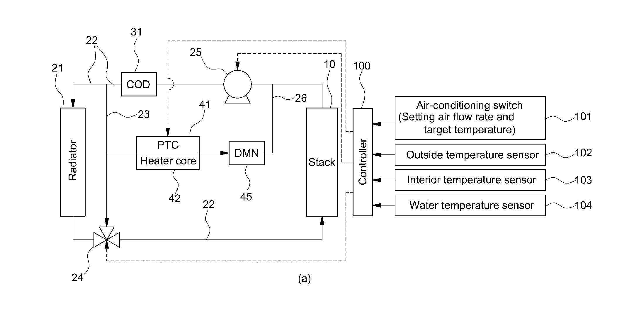
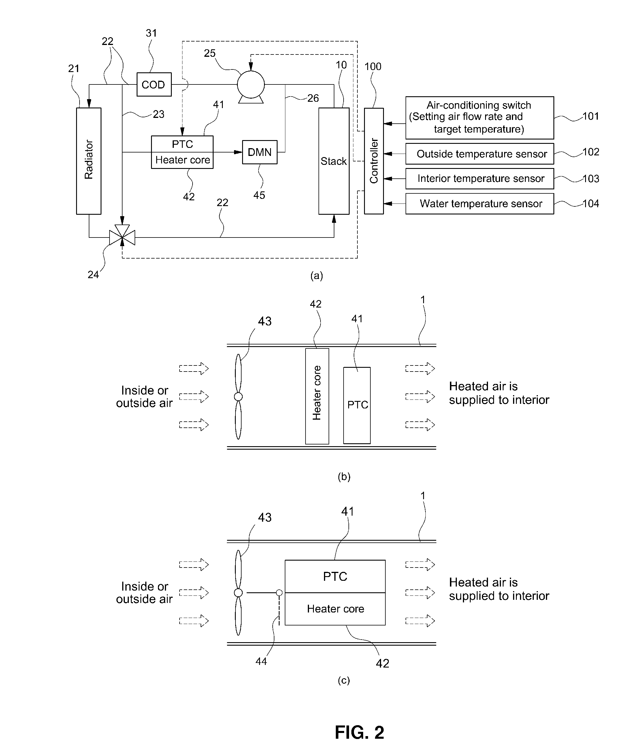
[0032]The present invention provides a heating control system and method for a fuel cell vehicle, in which a heater core through which coolant of a fuel cell stack passes, is used as an additional heating source together with a typical electric heater. As such, waste heat of coolant can be used to heat the interior of the vehicle.

[0033]FI...


PUM


Abstract

The present invention provides a heating control method for a fuel cell vehicle, in which an additional heating source is used together with a typical electric heater to reduce power consumption and increase fuel efficiency as compared to the sole use of the electric heater. For this purpose, the present invention provides a heating control method for a fuel cell vehicle which comprises an electric heater for heating air supplied to the interior of the vehicle, and a heater core provided in a coolant line for cooling a fuel cell stack and heating the air supplied to the interior of the vehicle by heat exchange with the coolant discharged from the fuel cell stack. The method comprises: detecting a state of charge (SOC) of a battery when the interior temperature is lower than a predetermined temperature set by a driver and, if the SOC of the battery is above a predetermined lower limit, heating the interior of the vehicle by operating the electric heater by the power of a battery; heating the interior of the vehicle by operating the electric heater by the power generated by the fuel cell stack, if the SOC of the battery is below the lower limit; heating the interior of the vehicle using both the heater core and the electric heater, if the temperature of the coolant is above a predetermined temperature at which the fuel cell stack does not reach a normal operating temperature; and heating the interior of the vehicle using only the heater core while turning off the electric heater, if the temperature of the coolant is increased above a normal operating temperature of the fuel cell stack.

Description

CROSS-REFERENCE TO RELATED APPLICATION[0001]This application claims under 35 U.S.C. §119(a) the benefit of Korean Patent Application No. 10-2010-0114234 filed Nov. 17, 2010, the entire contents of which are incorporated herein by reference.BACKGROUND[0002](a) Technical Field[0003]The present invention relates to a heating control method for a fuel cell vehicle. More particularly, it relates to a heating control method for a fuel cell vehicle, in which an additional heating source, which uses waste heat of coolant of a fuel cell stack, is used together with a typical electric heater.[0004](b) Background Art[0005]Internal combustion engines using fossil fuels have many problems such as environmental pollution due to exhaust gas, global warming due to carbon dioxide, respiratory diseases due to increased ozone, etc. Moreover, since the amount of fossil fuels left on earth is limited, they will be exhausted in the near future.[0006]To address the above-described problems, various types ...

Claims


Application Information

Patent Timeline
IPC IPC(8): H01M8/04F25B27/00B60H1/02B60H1/32
CPCB60H1/2218B60H1/2225B60H1/00392H01M16/006H01M8/04067Y02B90/16H01M8/04753H01M2250/20H01M2250/405Y02E60/50Y02T90/32H01M8/0432Y02B90/10Y02E60/10Y02T90/40B60H1/00278B60H1/143
Inventor LEE, SEUNG YONGKIM, CHI MYUNGKIM, EUNG YOUNGNAM, GI YOUNGNA, SUNG WOOKKIM, HARK KOOHAN, KWANG OKLIM, KYOON SOOPARK, YONG SUN
Owner HYUNDAI MOTOR CO LTD
Why Eureka
Try Eureka