Method of arraying ferritin

Active Publication Date: 2012-05-17
PANASONIC INTELLECTUAL PROPERTY MANAGEMENT CO LTD
View PDF1 Cites 3 Cited by
  • Summary
  • Abstract
  • Description
  • Claims
  • Application Information

AI Technical Summary

Benefits of technology

[0035]According to the method of arraying ferritin of the present invention, selectively arraying ferritin, in turn, inorganic particles contained in ferritin at a chromium, molybdenum, or tungsten portion formed on a part of silicon oxide can be realized.

Problems solved by technology

However, NPL 4 fails to disclose any mechanism of occurrence of the difference of adsorption on the hydrophilic substrate, titanium, and on silicon.

Method used


Image

  • Method of arraying ferritin
  • Method of arraying ferritin
  • Method of arraying ferritin

Examples


example 1

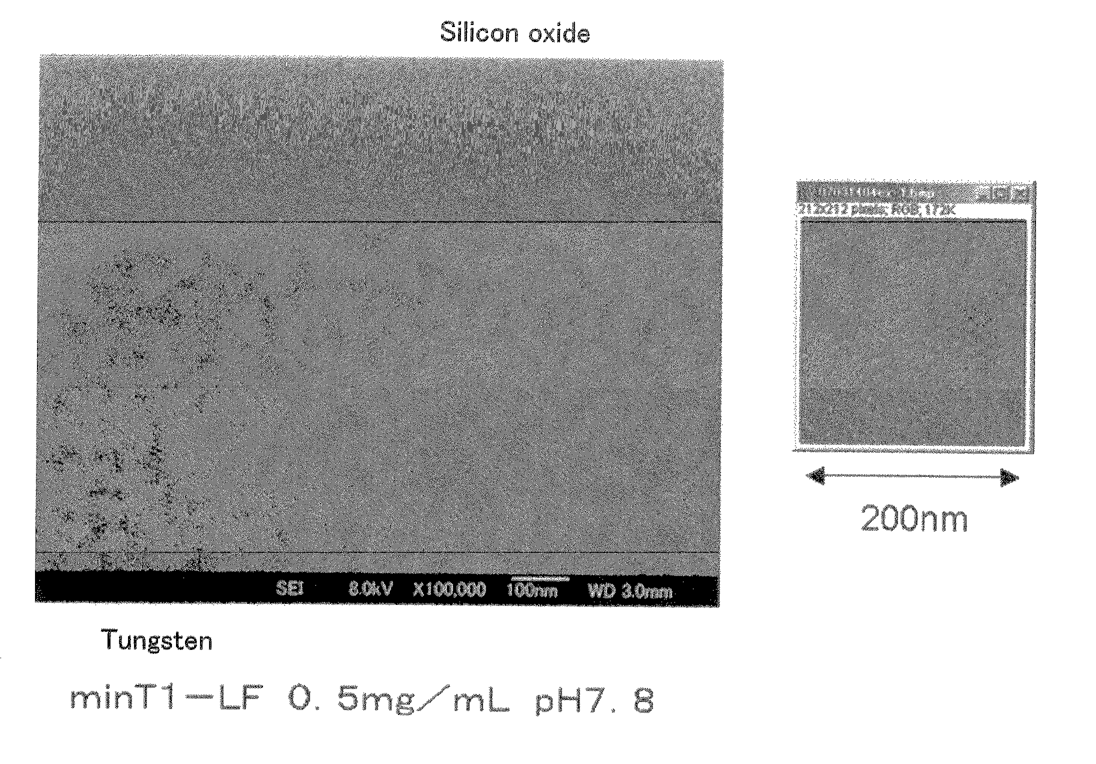
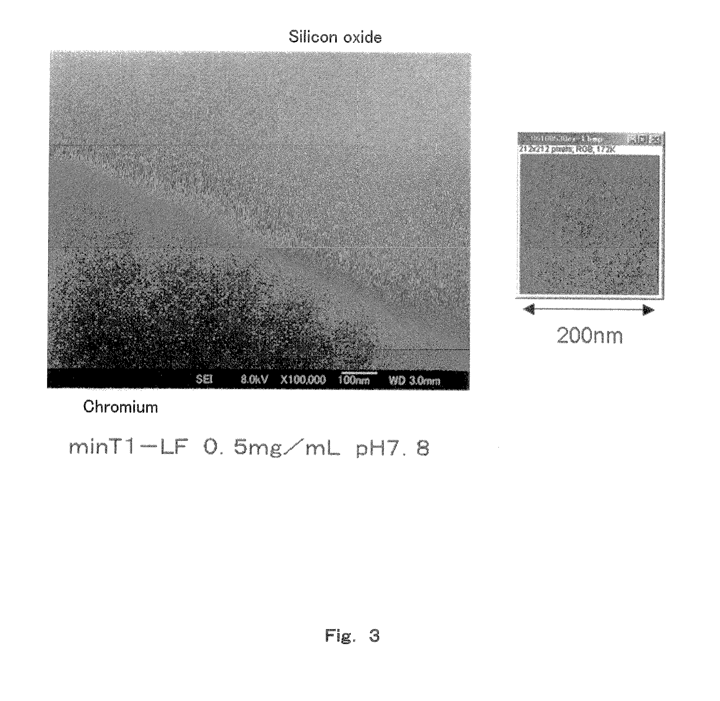
[0058]First, a method of producing ferritin used in Examples below is explained. In Examples of the present application, recombinant ferritin “minT1-LF” modified with a polypeptide set out in SEQ ID NO: 1 at the N-terminal, and recombinant ferritin “Δ1-LF” not having the sequence set out in SEQ ID NO: 1 were used.

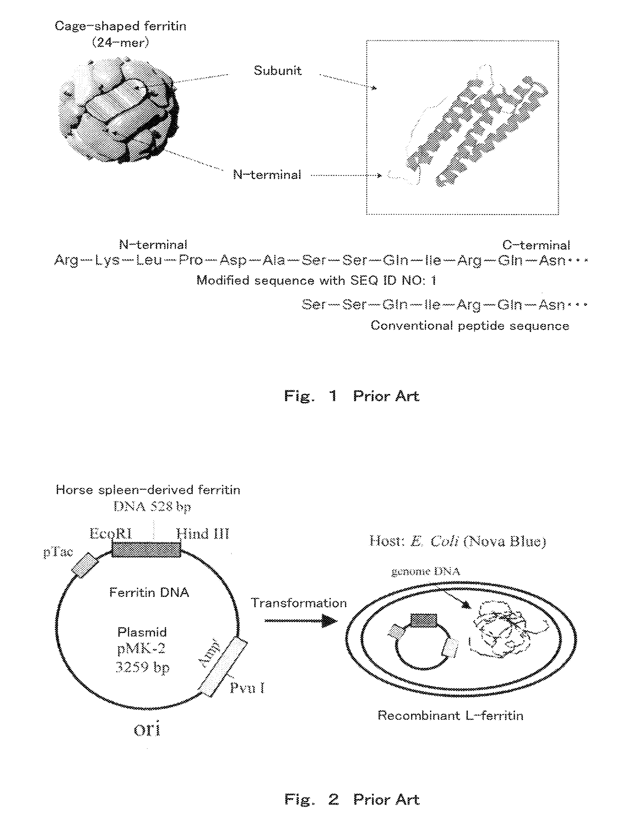
[0059]First, a method of producing Δ1-LF is explained. Since there are L-type and H-type subunits of natural horse spleen-derived ferritin having slightly different structures, natural ferritin does not have a certain structure. Thus, in Examples of the present application, recombinant ferritin consisting only of the L-type subunit was used.

[0060]The DNA (SEQ ID NO: 2,528 base pairs) coding for L-type ferritin was first amplified using a PCR method to provide a large amount of L-type ferritin DNA. Next, this L-type ferritin DNA was cut at specific sites (restriction enzyme sites) with restriction enzymes EcoRI and HindIII. A solution of an L-type ferritin DNA fragment havin...

example 2

[0086]50 mM MES-Tris prepared to have a pH each adjusted to 6.7, 7.4, 7.8, 8.0 and 8.2 were used as the buffer, and solutions were prepared having a ferritin concentration of 2.0 mg / mL and a nonionic surfactant (Tween 20) concentration of 1 v / v %.

[0087]Then, a binding step similar to that in Example 1 was carried out using this solution. SEM images of the substrate surface after the binding step are shown in FIG. 6, and the results of measurement of the number of the minT1-LF are shown in FIG. 7. When the pH was 7.4 or 6.7, the minT1-LF was likely to aggregate in the solution, and thus the solution became turbid immediately after mixing at pH 6.7, and after several minutes passed at pH 7.4. Thus, aggregates were frequently found also for the minT1-LF arrayed on the solid surface. Although the results of measurement for the portion other than the aggregates are shown in FIG. 7, it was difficult to obtain stable results at a pH lower than 7.4. It was necessary to complete the operatio...

example 3

[0092]To a solution containing 50 mM MES-Tris (pH 7.8) as the buffer, and ferritin at a concentration of 0.5 mg / mL, was added a nonionic surfactant Tween 20 at each concentration of 0.005, 0.01, 0.1, 1, 5, 10, 15 and 20 v / v % to prepare solutions. These solutions were added to a silicon oxide / tungsten substrate dropwise, and subjected to the binding step.

[0093]The nonionic surfactant has a high viscosity, and is likely to form bubbles; therefore, reproducible results were not obtained when the concentration of the nonionic surfactant was 15 v / v % or 20 v / v %. The number of array of the minT1-LF was almost constant at a tungsten portion. On the silicon oxide substrate, the array number abruptly increased when the concentration was lower than 0.01 v / v %, and the number was almost the same as that on tungsten when the concentration was 0.005 v / v %. From the foregoing results, the minT1-LF achieved selectivity of array to the tungsten portion at a concentration of the nonionic surfactan...


PUM


Abstract

A method of selectively arraying ferritin and inorganic particles on a silicon oxide substrate having a chromium, niobium or tungsten portion. An aspect of the method includes steps of: preparing a solution which contains ferritin modified at an N-terminal part of a subunit with a peptide set out in SEQ ID NO: 1, and a nonionic surfactant; and a binding step of bringing the solution in contact with the silicon oxide substrate to selectively array peptide-modified ferritin to the chromium, niobium or, tungsten portion. Another aspect of the method includes selectively arraying ferritin modified with the peptide set out in SEQ ID NO: 1, and the inorganic particles contained in ferritin at the chromium, niobium, or tungsten portion by removing the solution.

Description

TECHNICAL FIELD[0001]The present invention relates to a method of selectively arraying ferritin at a chromium, molybdenum, or tungsten portion formed on a silicon oxide substrate. The present invention also relates to a method of selectively arraying inorganic particles contained in ferritin on a silicon oxide substrate at a chromium, molybdenum, or tungsten portion.BACKGROUND ART[0002]In known conventional methods for arraying ferritin or inorganic particles contained in ferritin on a solid, arraying is carried out by way of electrostatic interaction on a pattern having electrostatically reversed polarity produced by a lithography technique (for example, see NPL 5).[0003]NPL 5 discloses: applying a resist on a silicon oxide substrate; developing the resist in areas exposed with electron beam lithography to remove the resist; exposing the areas on which the silicon oxide substrate was exposed to a vapor of a silane coupling agent having an amino group attached to the end, specifical...

Claims


Application Information

Patent Timeline
IPC IPC(8): B01J21/06H01B1/00
CPCC07K14/47B82Y5/00C07K14/79G01N2333/79
Inventor MATSUKAWA, NOZOMU
Owner PANASONIC INTELLECTUAL PROPERTY MANAGEMENT CO LTD
Why Eureka
Try Eureka