Device and method for combusting particulate substances

a technology of combusting device and particulate matter, which is applied in the direction of vapor flow control, magnetic separation, machines/engines, etc., can solve the problem of reducing the life of the filter

Inactive Publication Date: 2012-05-24
UTSUNOMIYA UNIV
View PDF6 Cites 13 Cited by
  • Summary
  • Abstract
  • Description
  • Claims
  • Application Information

AI Technical Summary

Problems solved by technology

Since the techniques in the above Patent Documents 1 and 2 are a technique in which particulate matters are captured by a heat resistant filter and the captured particulate matters are heated to be combusted away in an arbitrary timing, there is concern about a reduced filter life due to a rapid temperature change, a local heating or the like.

Method used


Image

  • Device and method for combusting particulate substances
  • Device and method for combusting particulate substances
  • Device and method for combusting particulate substances

Examples


embodiment

[0047]Representative three embodiments of a combustion device for combusting particulate matters of the present invention will be described in detail with reference to the drawings.

first embodiment

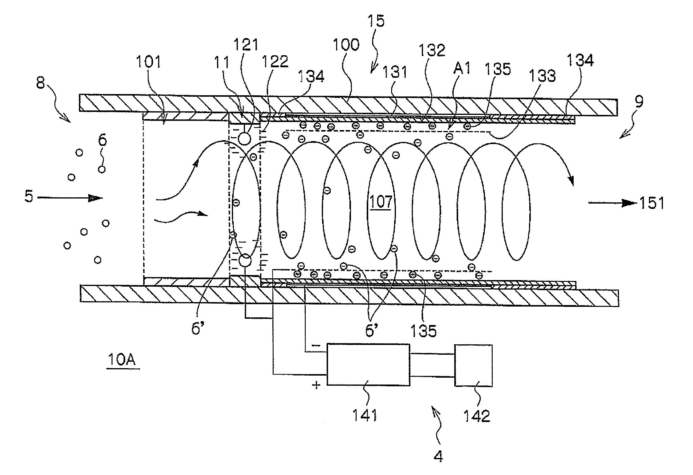
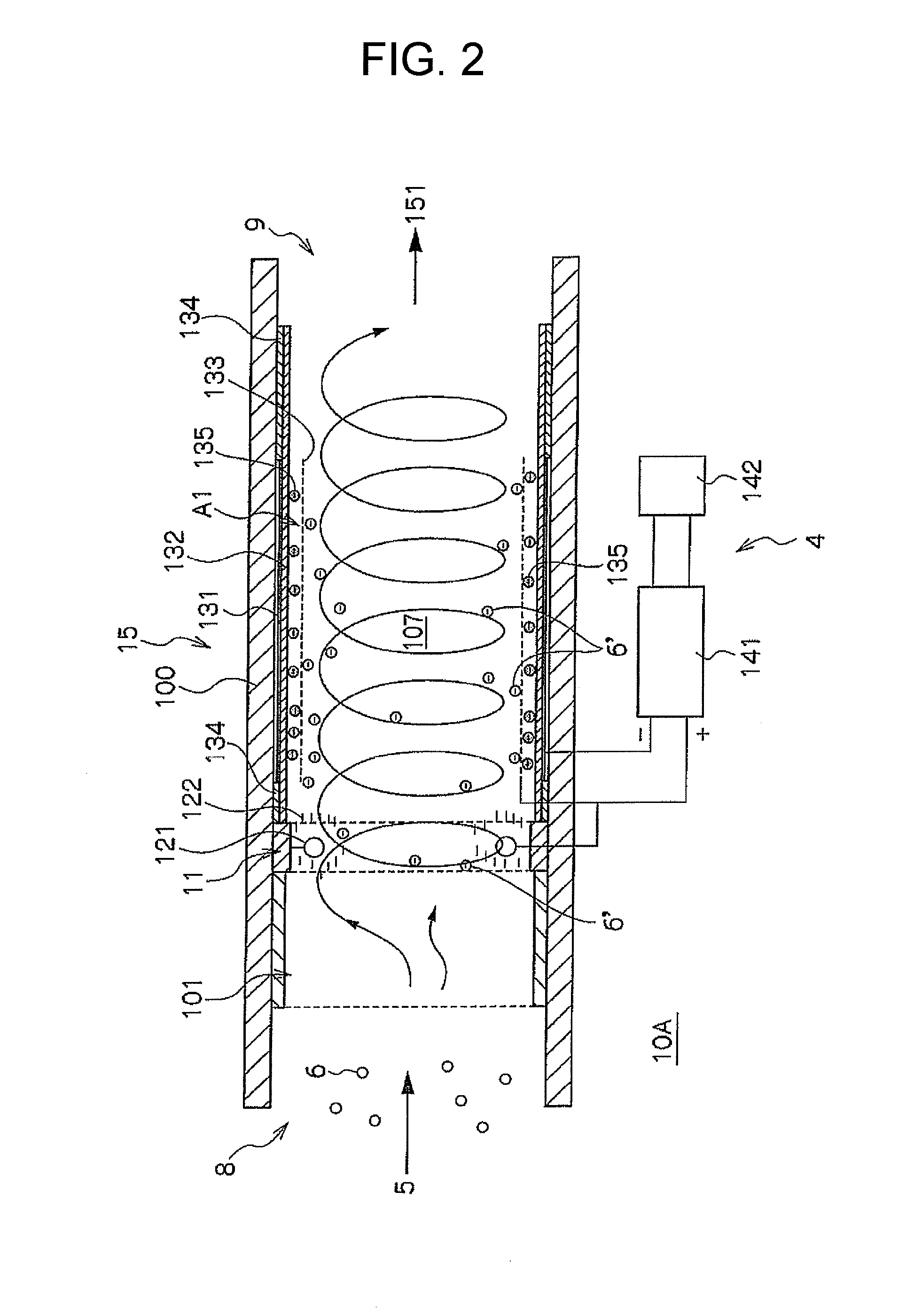
[0048]As shown in FIG. 2, the first embodiment of combustion device 10A for combusting particulate matters is configured so as to electrostatically attract particulate matter 6′ on which negative charge 122 is charged to cylindrical mesh anode 133, which is provided on the downstream side, and to retain particulate matter 6′ at silent discharge area A1, in order to increase the retention time at silent discharge area A1. Specifically, as shown in FIG. 2, the device 10A includes introduction portion 8, charging unit 11, electric discharge unit 15, discharge portion 9 and power source unit 4.

[0049]As shown in FIG. 2, combustion device 10A is preferably configured to have introduction portion 8, charging unit 11, electric discharge unit 15 and discharge portion 9 in the order mentioned toward the downstream side in insulation pipe 100. Each of the portions may be connected to each other as a separate member in the order mentioned toward the downstream side. Further, combustion device 1...

second embodiment

[0074]As shown in FIG. 7, the second embodiment of combustion device 10B for combusting particulate matters is configured so electrostatically attract particulate matter 6′, which has negative charge 222, to cylindrical mesh anode 233 which is provided on the downstream side of the flow channel, and can capture particulate matter 6′ and to deposited particulate matter 6′on cylindrical mesh anode 233, in order to increase the retention time at silent discharge area A2. Specifically, as shown in FIG. 7, the combustion device 10B includes introduction portion 8, charging unit 21, electric discharge unit 25, discharge portion 9 and power source unit 4 in the order mentioned toward the downstream side. Although, in the example in FIG. 7, charging unit 21 and electric discharge unit 25 are configured as one in insulation pipe 100, charging unit 21 and electric discharge unit 25 may not be necessarily configured as one.

[0075]In the same manner as in the first embodiment, introduction porti...


PUM


Abstract

It is possible to provide a device and a method for combusting particulate substances which particulate matters discharged from an internal combustion engine can be effectively combusted, and the device configuration is simple and does not become large and heavy. The combustion device has: an introduction portion 8 used to introduce a particulate matter-containing gas 5 discharged from the exhaust port of an internal combustion engine; a charging unit 11 which is provided on the downstream side of the introduction portion 8, and in which all or part of the particulate matters 6′ are e negatively charged by bringing the particulate matter-containing gas into contact with; an electric discharge unit 15 which is provided in an insulation pipe 100 which is connected to the downstream side of the charging unit 11, and in which the particulate matters 6′, all or part of which are negatively charged, are introduced into a silent discharge area A1 and are combusted with an increased retention time, the silent discharge area being generated between an anode and a cathode; a discharge portion 9 which is connected to the insulation pipe 100 at the downstream side of the electric discharge unit and which discharges the combusted gas; and a power source unit which applies an electric field to the charging unit and the electric discharge unit.

Description

FIELD OF THE INVENTION[0001]The present invention relates to a device and a combustion method for combusting particulate matters in which particulate matters discharged from an internal combustion engine can be effectively combusted.BACKGROUND ART[0002]A variety of techniques have been studied to remove particulate matters (PM) in exhaust gas discharged from an internal combustion engine. In Patent Document 1, a technique is proposed in which particulate matters are captured by a ceramic honeycomb filter, and when the amount of the captured particulate matters exceeds the predetermined acceptable value, the captured particulate matters are heated to be combusted away. In Patent Document 2, in order to overcome the drawback that the ceramic honeycomb filter used in Patent Document 1 is expensive, fragile and hard to handle, and in order to decrease the power consumption required for burning away particulate matters, a technique is proposed in which a combustion heater is placed betwe...

Claims


Application Information

Patent Timeline
Patent Type & Authority Applications(United States)
IPC IPC(8): F01N3/02B03C3/36B03C3/40B03C3/017
CPCB03C3/363B03C3/41B03C3/49B03C2201/30F01N3/01B03C3/62F01N3/0892B03C3/06B03C3/09B03C3/12B03C3/47F01N3/027
Inventor NAGASAWA, TAKESHI
Owner UTSUNOMIYA UNIV
Why Eureka
Try Eureka