Light source device and image display apparatus

a technology of light source and image display, which is applied in the direction of lighting and heating equipment, instruments, optics, etc., can solve the problems of complex maintenance, short life of light source, and deterioration of image quality, and achieve compact, bright and efficient light source

Active Publication Date: 2012-05-24
PANASONIC CORP
View PDF8 Cites 99 Cited by
  • Summary
  • Abstract
  • Description
  • Claims
  • Application Information

AI Technical Summary

Benefits of technology

[0015]The present invention has been achieved in view of the above circumstances, and its object is to provide a light source device capable of highly efficiently extracting and propagating fluorescence emitted from a phosphor layer by irradiation of excitation light by a compact and simple optical system.
[0020]When the phosphor layer is arranged on the z=0 plane and excitation light is irradiated from a z>0 direction to the point of x=y=0, the intensity of fluorescence emitted from the phosphor has a light distribution close to Lambertian having peaks in positive and negative z-axis directions, and the ratio of the fluorescence emitted to the z>0 region is higher. Therefore, as in the present invention, by making the incident region of the excitation light and the exiting region of fluorescence emitted from the phosphor belong to the space on the same side with respect to the face of the phosphor layer, it is possible to extract and propagate fluorescence highly efficiently.
[0024]As the dichroic mirror, a characteristic of transmitting the p-polarized component and reflecting the s-polarized component in the dominant wavelength of the excitation light is selected. By configuring the dichroic mirror to have such an optical spectrum characteristic, the excitation light component also can be extracted easily in the same direction as the fluorescence, as output light from the light source device.
[0026]According to the present invention, by making the incident region of the excitation light and the exiting region of fluorescence emitted from the phosphor belong to the space on the same side with respect to the surface on which the phosphor layer is placed, the fluorescence on a side where a larger amount of fluorescence is emitted can be utilized effectively, whereby a compact, bright and efficient light source device can be realized.

Problems solved by technology

However, when using the high-pressure mercury lamp as a light source, there are problems of a short lifetime of the light source, complex maintenance, etc.
However, due to the high coherency of the laser light, a speckle noise is generated, which deteriorates image quality.
Specifically, as to the laser light in wavelengths ranging from green to yellow where the human eye has high visibility, the decrease in image quality due to the speckle noise is a large problem.
Further, although, in the LED light source, the speckle noise does not become a serious problem, a low light density of the light source due to a large light-emitting area makes it difficult to obtain a high-brightness image display apparatus.
Further, even when the laser light source is used as the excitation source, a speckle noise is not generated because the fluorescence itself obtained by frequency conversion is incoherent light.
However, since a large amount of fluorescence from the phosphor layer is emitted in a space on the same side as the excitation light source when seen from the base on which the phosphor is disposed, it is difficult to obtain a high-efficiency light source device by the aforementioned conventional configuration.
Thus, this light source device requires such an optical system dedicated to propagating blue light, which results in the complicated device configuration.

Method used


Image

  • Light source device and image display apparatus
  • Light source device and image display apparatus
  • Light source device and image display apparatus

Examples


embodiment 1

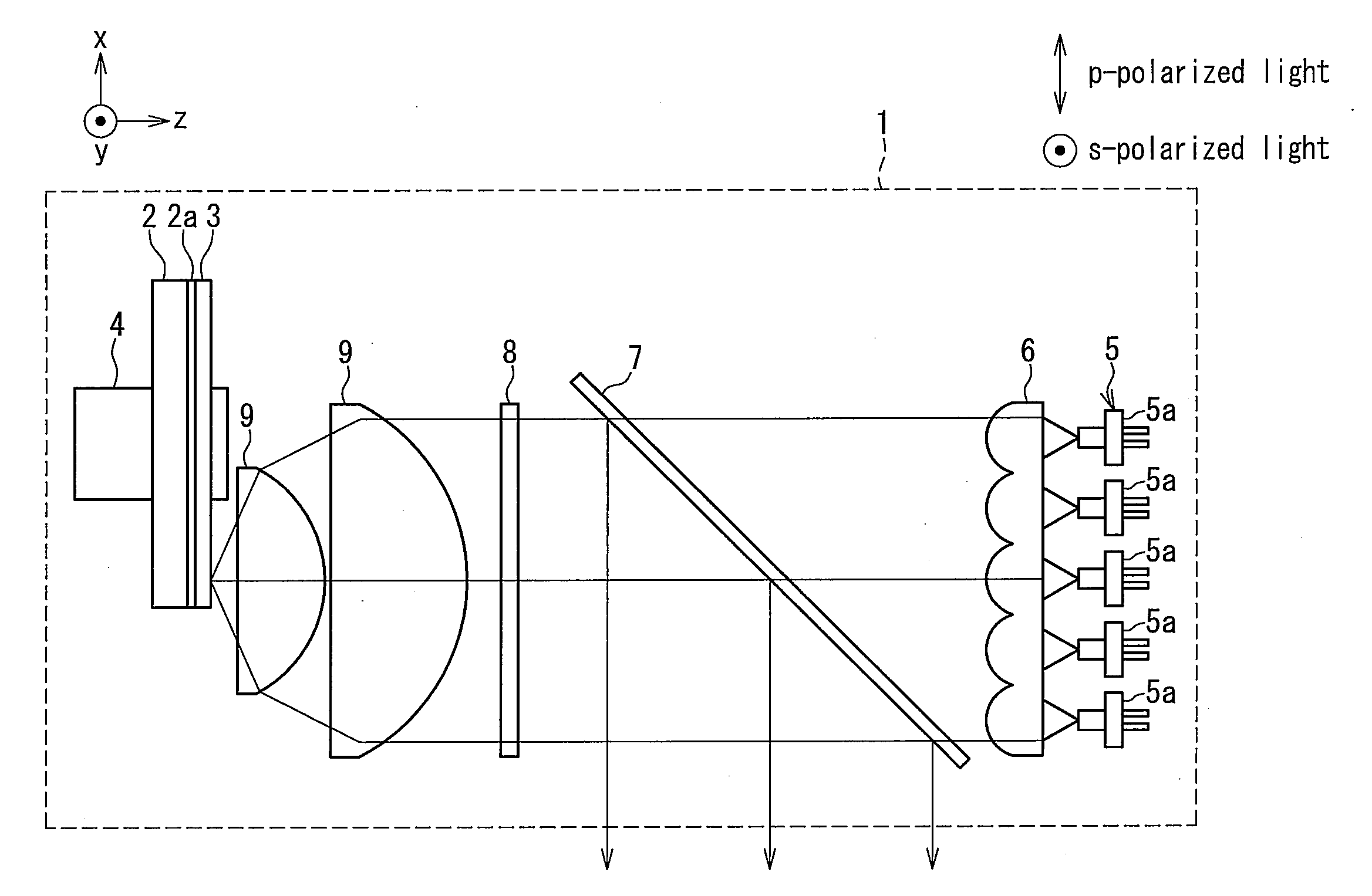
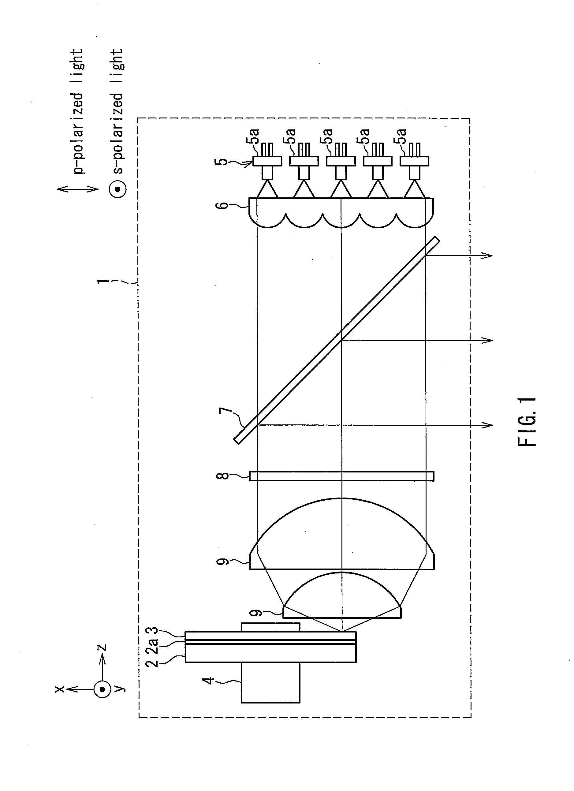
[0064]FIG. 1 shows a configuration of a light source device 1 in Embodiment 1. Output light of the light source device 1 contains light ranging from green to yellow as a main component and also a blue light component, and can be used as illumination light of an image display apparatus, etc.

[0065]A base 2 is a parallel plate of a glass. A dichroic coating 2a reflecting visible light highly efficiently is applied on one side surface of the base 2, and a phosphor mainly emitting green fluorescence is applied as a thin film on the dichroic coating 2a to form a phosphor layer 3. When x-y-z coordinate axes are set as shown in FIG. 1, the base 2 on which the phosphor layer 3 is formed has a circular shape in an xy plane, and can be rotated around the z-axis with a rotation device 4.

[0066]An excitation light source 5 is composed of a plurality of laser diodes 5a for obtaining a high-brightness light source device. The laser diode 5a is a blue laser diode oscillating in the vicinity of a wav...

embodiment 2

[0090]FIG. 4 shows a configuration of a light source device 14 in Embodiment 2. Output light of the light source device 14 contains light ranging from green to yellow as a main component and also a blue light component, and can be used as illumination light of an image display apparatus, etc. Although the constituent elements of the light source device 14 substantially are similar to those in Embodiment 1, the optical spectrum characteristic of a dichroic mirror 15 is different from that of the dichroic mirror in Embodiment 1. Accordingly, the arrangement of the elements is different from Embodiment 1. In the following description, the same elements as those in Embodiment 1 are given the same reference numerals, and the repeated descriptions will be omitted.

[0091]An excitation light source 16 and the phosphor layer 3 used in the present embodiment are the same as those in Embodiment 1. However, outgoing light from the excitation light source 16 is adjusted to be s-polarized light. T...

embodiment 3

[0094]A light source device in Embodiment 3 will be described with reference to FIGS. 6A and 6B. Since the present embodiment is equivalent to the configuration of Embodiment 1 expect for a phosphor layer part formed on the base, the illustration of the entire configuration of the light source device will be omitted. The descriptions regarding the same elements will be omitted. Output light from the light source device of the present embodiment contains light ranging from green to yellow, red light as main components and a blue light component, and can be used as illumination light of an image display apparatus, etc.

[0095]As shown in FIG. 6A, although a configuration composed of the base 2, the dichroic coating 2a, and the rotation device 4 is identical to that of Embodiment 1, a configuration of a phosphor layer 17 formed on the dichroic coating 2a is different from that of Embodiment 1. Specifically, in the present embodiment, as shown in FIG. 6B, a surface of the disk-shaped base...


PUM


Abstract

A light source device includes a phosphor layer formed on a base, and an excitation light source exciting the phosphor. A dichroic mirror is arranged between the phosphor layer and the excitation light source and inclined with respect to a propagation direction of excitation light from the excitation light source. An incident region of the excitation light and an exiting region of fluorescence emitted from the phosphor belong to a space on the same side with respect to the surface with the phosphor layer disposed. In a dominant wavelength of the excitation light, the dichroic mirror has a spectral characteristic of transmitting 50% or more of light of a p-polarized component and reflecting 50% or more of light of a s-polarized component. Fluorescence emitted from the phosphor layer can be extracted highly efficiently and propagated by a compact and simple optical system.

Description

BACKGROUND OF THE INVENTION[0001]1. Field of the Invention[0002]The present invention relates to a light source device using fluorescence emitted from a phosphor by excitation light, and in particular to a light source device emitting visible light of red, green and blue for use in an image display apparatus.[0003]2. Description of Related Art[0004]Recently, a projector as an image display apparatus that magnifies and projects various video images on a screen has been used widely. Such a projector has a function of condensing light emitted from a light source onto a spatial light modulation element such as a digital micromirror device (DMD) or a liquid crystal display element, and displaying exiting light from the spatial light modulation element modulated by video signals on a screen as color video images.[0005]In order to obtain a bright and large-screen video image with the projector, conventionally, a high-brightness high-pressure mercury lamp has been used as a light source. Ho...

Claims


Application Information

Patent Timeline
Patent Type & Authority Applications(United States)
IPC IPC(8): G03B21/28F21V7/00
CPCG03B21/204G03B21/2066H04N9/3161H04N9/3158G03B33/12
Inventor KITANO, HIROSHITANAKA, TAKAAKI
Owner PANASONIC CORP
Why Eureka
Try Eureka