
Hybrid free-air gas turbine engine

a gas turbine engine and free-air technology, applied in the direction of machines/engines, waterborne vessels, climate sustainability, etc., can solve the problems of high acquisition and operating costs of aviation

Inactive Publication Date: 2012-05-24
SHELLEY RUDOLPH ALLEN
View PDF0 Cites 22 Cited by
  • Summary
  • Abstract
  • Description
  • Claims
  • Application Information

AI Technical Summary

Benefits of technology

[0010]Simplicity, and if at all possible, less costly technology to reduce powerplant cost is a barrier that is limiting general aviation advancement, and is a primary cause for the high acquisition and operating costs associated with aviation.
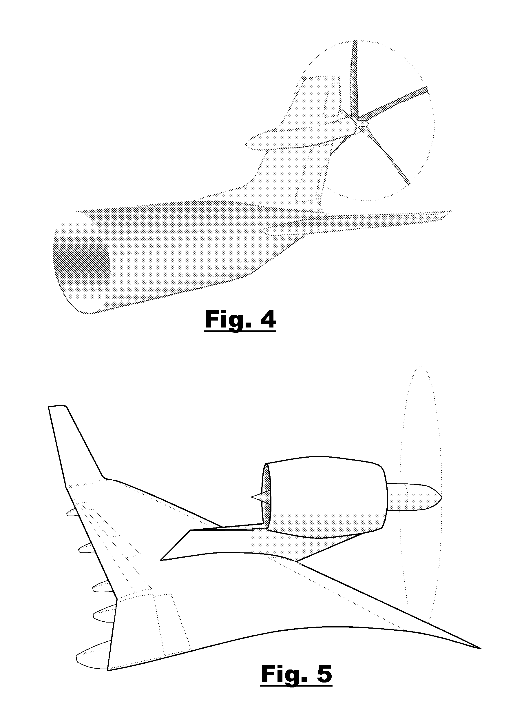
[0013]Modularity: There is the necessity of mounting engines on an airframe (or other air-enveloped vehicle) in places where they can operate at their peak, yet be protected from damage, as far as is practical. This must be reconciled with vehicular design parameters predicated on performance, ease of construction, load carrying accommodation, maintenance access and other factors. Therefore, the freedom to distribute a complete propulsion system in partial modules remotely on an airframe (or other air-enveloped vehicle) as component modules would relieve some constraints on the accommodation of that system as a whole, where linkages between modules would not themselves be prohibitively complex.
[0015]Reduced Aerodynamic Drag: A design that facilitates aerodynamic shape, i.e., a smaller frontal area, compared to current turbofan engines within a given thrust class.

Problems solved by technology

Simplicity, and if at all possible, less costly technology to reduce powerplant cost is a barrier that is limiting general aviation advancement, and is a primary cause for the high acquisition and operating costs associated with aviation.
Higher Responsiveness: Gas turbine engines have a degree of response lag that is partially overcome by modern full authority digital engine controls (FADEC), but as yet is not as immediate as pilots might require in some emergency situations.

Method used


Image

  • Hybrid free-air gas turbine engine
  • Hybrid free-air gas turbine engine
  • Hybrid free-air gas turbine engine

Examples


Embodiment Construction

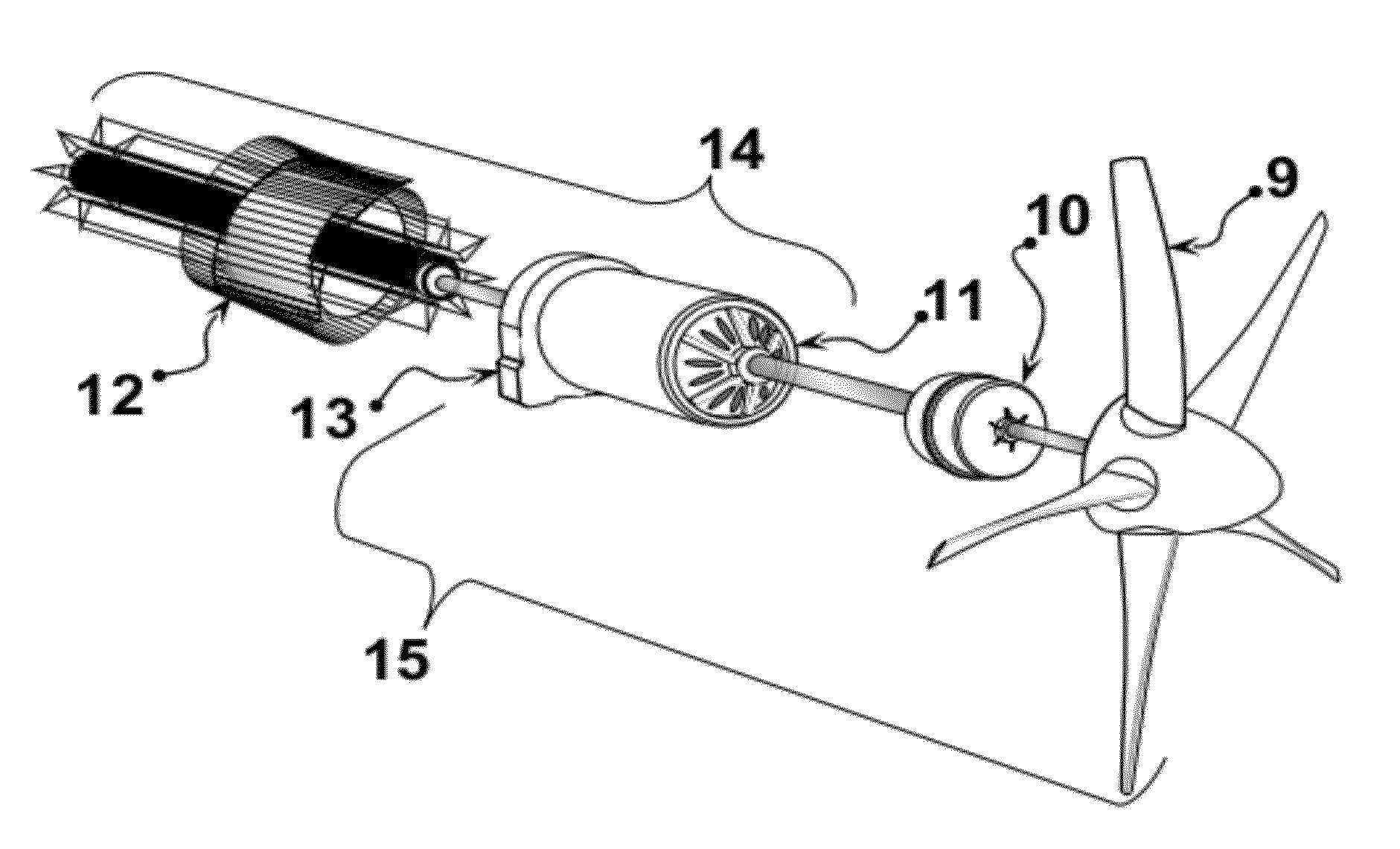
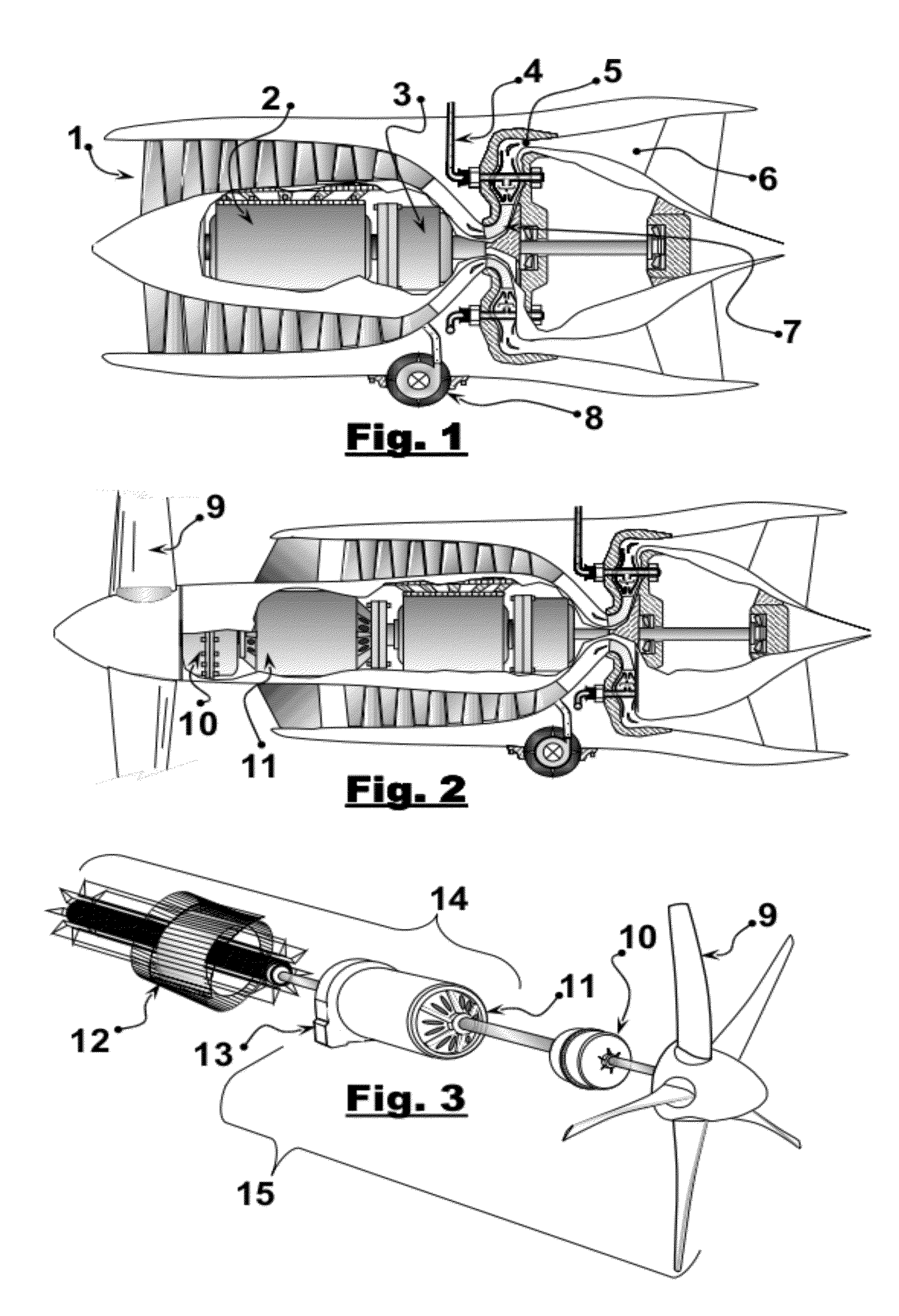
[0039]The invention may be visualized as being composed of three major component modules, where a conventional turbocompressor section using axial and / or centrifugal stages is still present as typical to conventional gas turbine engines.

[0040]In contradiction to conventional design, however, this invention has a compressor section that is not powered by a hot section (gas generator) power turbine mechanically linked to it by a rotating shaft, but is instead powered by one or more high-output electric motors; followed by fuel burners and then an exhaust nozzle. This portion of the engine is referred to as the ‘thrust module’. No advance over prior art is intended in the combustion or the exhaust nozzle, though it will be explained later that combustion section components must be engineered, using established technology, for its stationary parts to accommodate much hotter ignited gas flows.

[0041]The turbocompressor configuration described above needs a source of electrical energy to p...


PUM


Abstract

An alternate means of generating the power to drive the compressor section of gas turbine engines is described. Electric motors embedded within gas turbines would rotate the compressor, and receive the requisite power to perform the compression work from: 1) either a high-capacity APU generator, or 2) from a relative-wind driven turbine in a hybrid power-sharing arrangement. The electric motor provides enhanced control of N1 rpm, assuring greater responsiveness to control inputs.

Description

CROSS-REFERENCE TO RELATED APPLICATIONS[0001]U.S. Patent Documents7,802,757Parsons et al.October 20107,111,449StebbingsSeptember 20066,981,366SharpeJanuary 20066,832,890BoothDecember 20046,467,725Coles et al.October 20026,398,491Joos et al.June 20025,068,590Glennon et al.November 19915,031,086Dhyanchand et al.July 19914,759,178JoyJuly 1988RE.30629DawsonJune 19813,705,775RiouxDecember 19723,662,975DriskillMay 19723,527,055RegoSeptember 19703,100,962NoeggerathAugust 19632,956,402RaeOctober 19602,883,828HowellApril 19592,531,761ZucrowNovember 1950STATEMENT REGARDING FEDERALLY SPONSORED RESEARCH OR DEVELOPMENT[0002]Not ApplicableREFERENCE TO A SEQUENCE LISTING, A TABLE, OR A PROGRAM LISTING COMPACT DISC APPENDIX[0003]Not ApplicableBACKGROUND OF THE INVENTION[0004]The invention relates to gas turbine engines. In particular, it relates to a device that would be used as a prime mover for aircraft or other high-speed vehicles, where the engine creates power through the combustion of fuels m...

Claims


Application Information

Patent Timeline
Patent Type & Authority Applications(United States)
IPC IPC(8): F01D15/08F01D15/10
CPCF05D2220/34Y02T50/44Y02T50/64B64D27/10B64D27/12F02K5/00B64D2027/026F01D15/10F02C7/32F02K3/06B64D27/14Y02T50/40Y02T50/60B64D27/026
Inventor SHELLEY, RUDOLPH ALLEN
Owner SHELLEY RUDOLPH ALLEN
Learn More