Reversible electroporation device for inducing cell apoptosis

Inactive Publication Date: 2012-05-24
IGEA
View PDF3 Cites 12 Cited by
  • Summary
  • Abstract
  • Description
  • Claims
  • Application Information

AI Technical Summary

Benefits of technology

[0013]It is an object of the present invention to provide a reversible electroporation device and method,

Problems solved by technology

This causes an irreversible damage to the cell membrane causing cell death.
The application of such

Method used


Image

  • Reversible electroporation device for inducing cell apoptosis
  • Reversible electroporation device for inducing cell apoptosis
  • Reversible electroporation device for inducing cell apoptosis

Examples


example 1

[0059]New Zealand white rabbits were used and two or more electrodes were introduced in the distal femur where both bone tissue and cartilage tissue are present. The electrodes were also introduced in the vertebral body of sheep.

[0060]The electrodes were introduced in the tissue through an incision in the skin. Stainless steel electrodes were used: two or four electrodes with a diameter of 0.7 mm for rabbits and 2 electrodes with a diameter of 1.2 mm for sheep.

[0061]At the end of the electroporation treatment, the electrodes were cut at the bone surface and the portion inside the bone was left where it is, as a marker for later analyses.

[0062]Two days after treatment, tetracycline was injected into the rabbits to render fluorescent the new bone laid by osteoblasts.

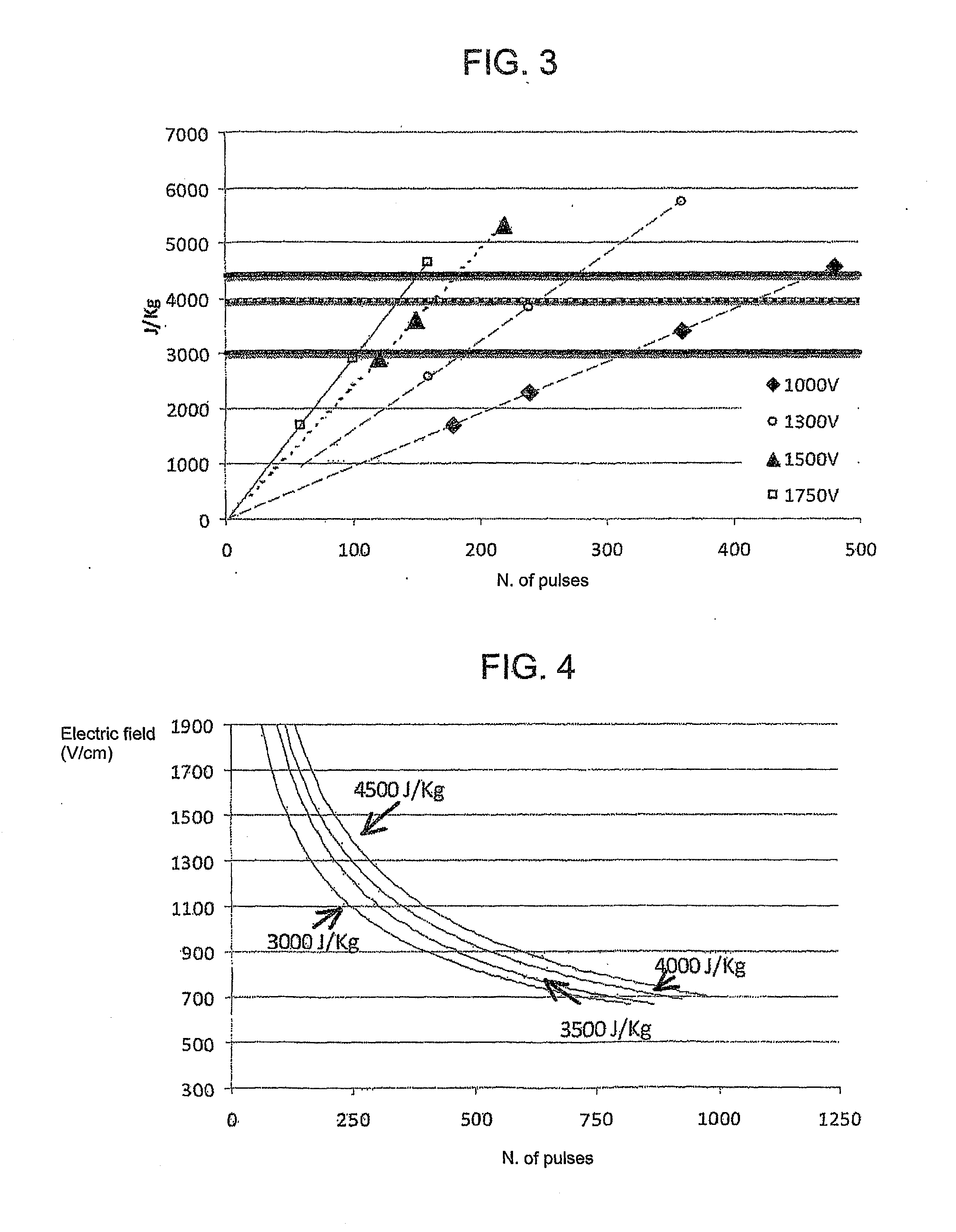
[0063]The experiments were performed in conditions implying the use of different values of electric field (1000, 1300, 1500 and 1750 V / cm) and a number of pulses from 60 to 480; electric pulses lasting 100 microseconds wer...

experiment 1

[0065]When a 1000 V / cm electric field was applied, an increasing number of pulses was respectively delivered: 180, 240, 360 and 480. All of the cells were ablated from the tissue when 480 pulses were used.

[0066]The following table shows the values of the absorbed dose with respect to the applied electric field and number of pulses.

TABLE 2Absorbed doseV / cmNumber of pulses(J / kg)10001801700100024022711000360340610004804542

[0067]An electroporation at 1000 V / cm, 180 pulses and absorbed dose of 1700 J / kg results in an ineffective ablation. FIG. 6A shows that the fluorescence image highlights the presence of a signal around the electrode. FIG. 6B shows a histological image of a staining with haematoxylin and eosin showing the presence of intact cells.

[0068]An electroporation at 1000 V / cm, 480 pulses and absorbed dose of 4542 J / kg instead results in an effective ablation. FIG. 7A shows that the fluorescence image highlights the absence of a signal around the electrode. FIG. 7B shows a histo...

experiment 2

[0069]When a 1300 V / cm electric field was applied, an increasing number of pulses was respectively delivered: 160, 240, 360. All of the cells were ablated from the tissue when 240 and 360 pulses were used.

[0070]The following table shows the values of the absorbed dose with respect to the applied electric field and number of pulses.

TABLE 3Absorbed energyV / cmNumber of pulses(J / kg)130016025501300240383313003605749

[0071]An electroporation at 1300 V / cm, 160 pulses and an absorbed dose of 2550 J / kg of the rabbit distal femur using a four electrode configuration results in an incomplete ablation of the cartilage (A) near the electrodes (B) (FIG. 8A). An electroporation at 1300 V / cm, 360 pulses and an absorbed dose of 5749 J / kg instead results in the complete ablation of the cartilage tissue (A) between the electrodes (B) (FIG. 8B).


PUM


Abstract

A reversible electroporation device in which an electric pulse generator generates a sequence of electric pulses delivered to electrodes coupled to a tissue in which a process of reversible electroporation that generates cell apoptosis is to be performed. The device is configured to control the amplitude of the pulses and the number of the pulses delivered to the electrodes so that the amount of energy per weight unit (absorbed dose) applied to the tissue is in a range between a first lower limit value of about 3000 J/kg and a second upper limit value of about 4500 J/kg.

Description

TECHNICAL FIELD[0001]The present invention relates to a reversible electroporation device and method adapted to induce cell apoptosis.BACKGROUND ART[0002]As is known, in many surgical and ablative treatments (e.g. directed to eliminate malignant or benign tumours), it is important to eliminate a specific pathological tissue without causing damage, or limiting it at minimum, to surrounding healthy tissues which do not need to be removed.[0003]In this field, irreversible electroporation treatments have recently been developed which are adapted to eliminate specific portions of target cell tissue leaving the surrounding portions unaltered.[0004]As is known, electroporation treatments provide for the application of electric pulses to a tissue by means of the use of electrodes applied to the tissue; the generated electric field induces the formation of pores in the cell membrane causing a variation thereof that promotes the flow of organic / inorganic substances (e.g. DNA or drugs) from th...

Claims


Application Information

Patent Timeline
IPC IPC(8): A61B18/00
CPCA61N1/327
Inventor CADOSSI, RUGGEROMARAZZI, DONATADE TERLIZZI, FRANCESCARONCHETTI, MATTIA
Owner IGEA
Why Eureka
Try Eureka