
Hoisting nacelle and tower

Inactive Publication Date: 2012-05-31
GENERAL ELECTRIC CO
View PDF5 Cites 18 Cited by
  • Summary
  • Abstract
  • Description
  • Claims
  • Application Information

AI Technical Summary

Benefits of technology

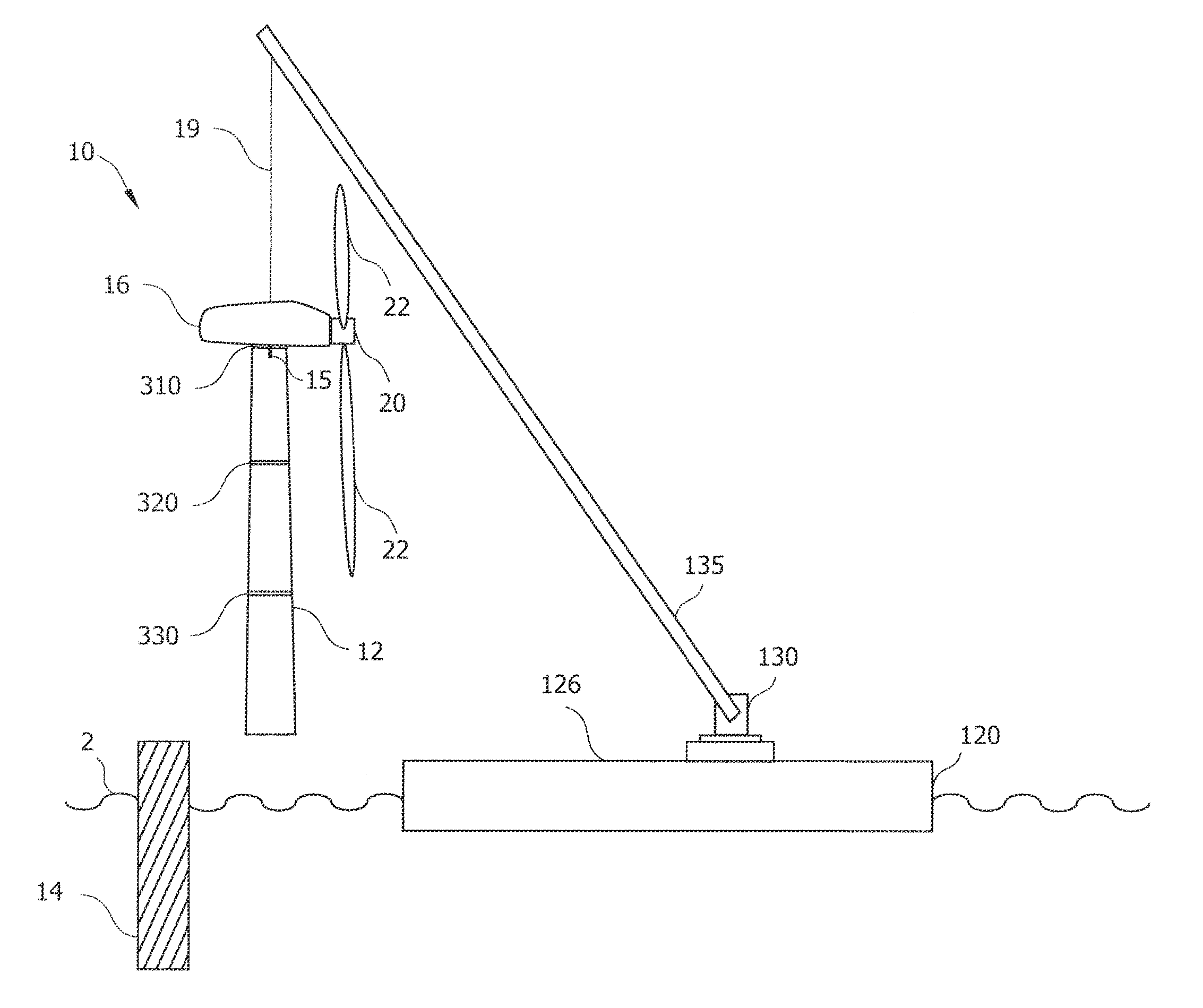
[0015]Since tower flanges are typically designed to take loads of a higher magnitude than the lifting loads, the linking elements may be attached to such flanges at or below the uppermost flange of a tower section. Attachment of the linking elements may be done by attaching elements, which are for instance lifting lugs that are permanently or removably attached to the flanges. In particular, compared to known hoisting methods, loading the lower flanges with the weight avoids that the thinner and more fragile upper tower parts carry the entire tower or turbine load during hoisting. The hoisting method described herein may be used to assemble or erect, maintain or disassemble wind turbines in a quick and cost efficient manner.

Problems solved by technology

Since the installation of wind turbines in offshore environments is typically done in calm weather conditions, rapidly changing weather and ocean swell may cause the window for installation of wind turbines to be brief and limited.
In general, costs for transport and installation of wind turbines are relatively high compared to their AEP.
Partly, this is due to the specialized and expensive equipment necessary for transport and assembly of wind turbines.
For instance, installing the often more than 100 m high wind turbines, which may also have rotor diameters of more than 80 m is typically done using specialized and expensive lifting cranes.
The length of dead times, i.e. the time until which weather and swell conditions are suitable for installation, may cause the retention time or on-call time for such equipment to be very long—this consequentially directly influences installation costs.
Further, maintenance and in exceptional cases decommissioning of wind turbines may rapidly add to the costs.
This is particularly the case for open water environments, which are generally not as accessible as environments on land and where installations of some wind turbines have required more than one lifting crane.

Method used


Image

  • Hoisting nacelle and tower
  • Hoisting nacelle and tower
  • Hoisting nacelle and tower

Examples


Embodiment Construction

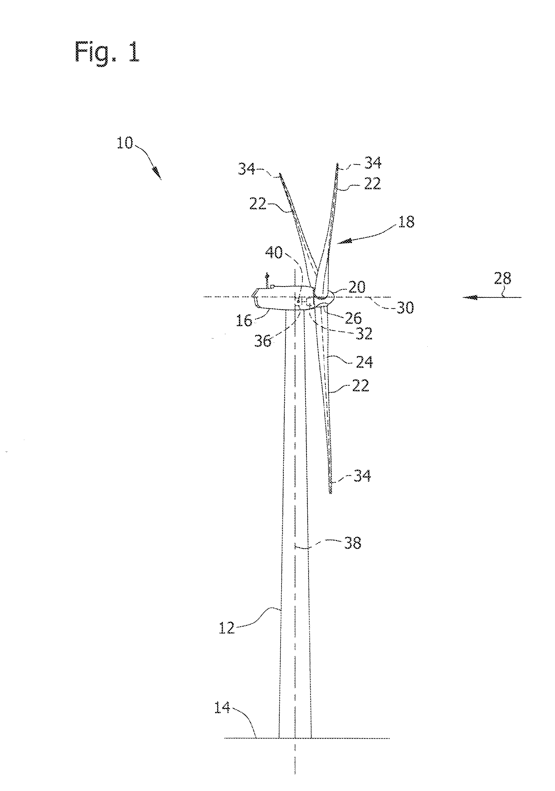
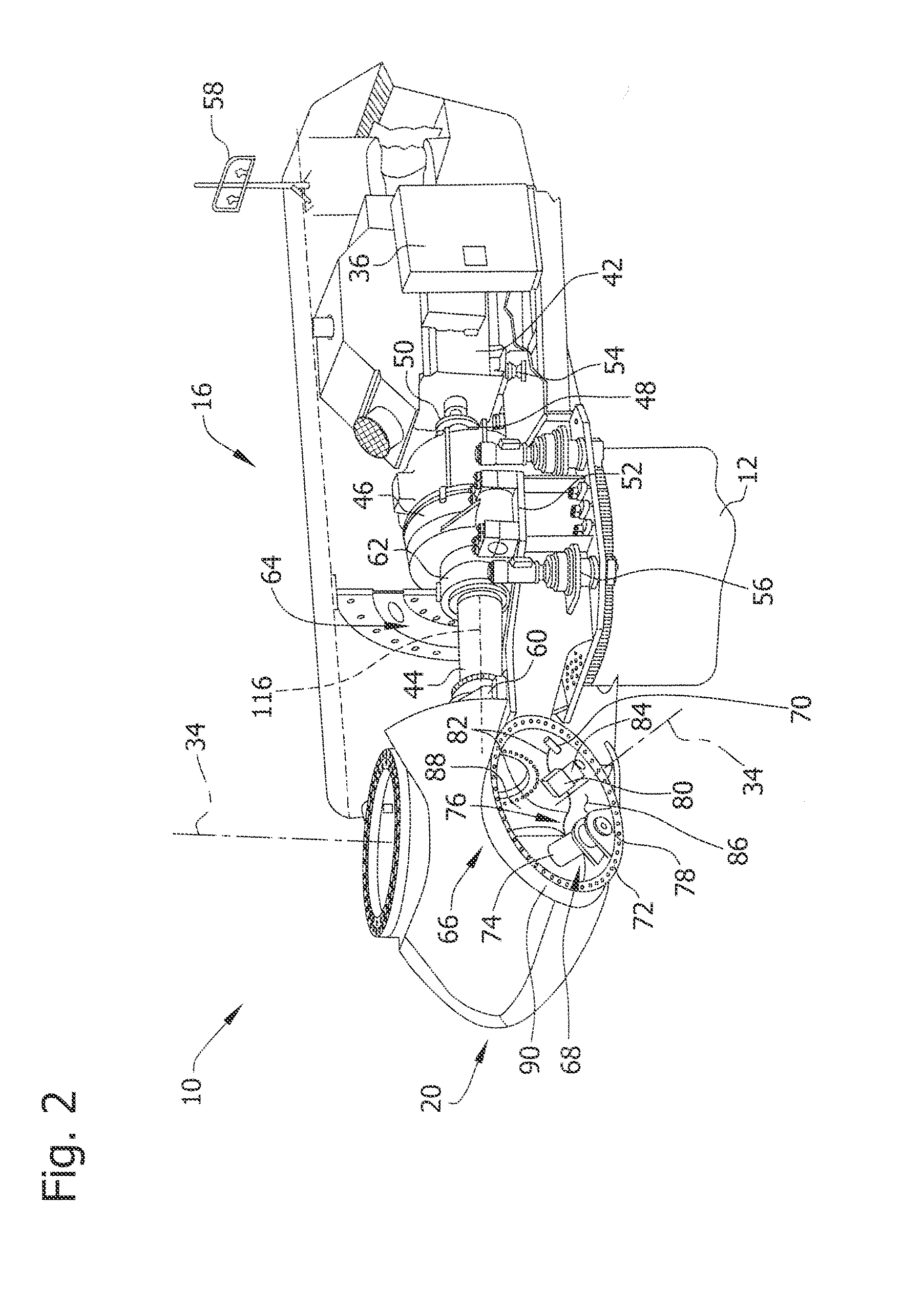
[0033]Reference will now be made in detail to the various embodiments, one or more examples of which are illustrated in each figure. Each example is provided by way of explanation and is not meant as a limitation. For example, features illustrated or described as part of one embodiment can be used on or in conjunction with other embodiments to yield yet further embodiments. It is intended that the present disclosure includes such modifications and variations.

[0034]As used herein, the term “wind turbine” is intended to be representative of any device that generates rotational energy from wind energy, and more specifically, converts kinetic energy of wind into mechanical energy. As used herein, the term “blade” is intended to be representative of any device that provides a reactive force when in motion relative to a surrounding fluid.

[0035]As used herein, the term “craft” is intended to be representative of any vessel capable of transporting a wind turbine or, one or more tower sectio...


PUM


Abstract

According to the present disclosure, a method for hoisting one or more tower sections (12, 25) of a wind turbine (10) or one or more tower sections (12, 25) of a wind turbine (10) preassembled to a nacelle (16), wherein the one or more tower sections (12, 25) include an uppermost flange (310, 320, 330, 340), is provided. The method includes: attaching one or more linking elements (19) to the one or more tower sections (12, 25) at or below the uppermost flange (310, 320, 330, 340); and hoisting the one or more tower sections (12, 25) of a wind turbine (10) or one or more tower sections (12, 25) of a wind turbine (10) preassembled to the nacelle (16) using a hoisting machine (130) that is connected with the one or more tower sections (12, 25) by the one or more linking elements (19).

Description

BACKGROUND OF THE INVENTION[0001]The subject matter described herein relates generally to methods and systems for wind turbines, and more particularly, to methods and systems for lifting one or more tower sections of a wind turbine, or one or more tower sections of a wind turbine preassembled to a nacelle in on- and offshore environments.[0002]In general, the electricity generated from wind by the construction and operation of clean, environmental and resource friendly wind turbines may be referred to as on- or offshore wind power depending on the environment in which the wind turbine is operating. Installing wind turbines in such environments usually requires specialized equipment and machinery such as lifting cranes capable of hoisting bulky objects with heavy loads.[0003]Onshore, wide open spaces that are sparsely populated and have strong prevailing winds, usually provide excellent locations for installing wind turbines with a high Annual Energy Production (AEP). Additionally, m...

Claims


Application Information

Patent Timeline
IPC IPC(8): E04H12/34E04H12/00B66C13/00
CPCB66C1/108Y02E10/728F03D1/001E04H12/342F03D13/10Y02E10/72
Inventor NIES, JACOB JOHANNES
Owner GENERAL ELECTRIC CO
Learn More