Magnetization reversal device, memory element, and magnetic field generation device

a technology of magnetic field generation and magnetic field, applied in semiconductor devices, digital storage, instruments, etc., can solve the problems of inability to solve the decline in the reduction of the magnetoresistance charge, the durability of spin thermal disturbance, etc., and achieve the effect of reducing the magnetoresistance charg

Inactive Publication Date: 2012-05-31
KYUSHU UNIV
View PDF4 Cites 9 Cited by
  • Summary
  • Abstract
  • Description
  • Claims
  • Application Information

AI Technical Summary

Benefits of technology

[0021]Nevertheless, none of the disclosed techniques could apply to magnetization reversal of a ferromagnetic dot (free layer) having a thickness of more than a spin diffusion lengt

Problems solved by technology

Nevertheless, none of the disclosed techniques could apply to magnetization reversal of a ferromagnetic dot (free layer) having a thickness of more than a spin diffusion length,

Method used


Image

  • Magnetization reversal device, memory element, and magnetic field generation device
  • Magnetization reversal device, memory element, and magnetic field generation device
  • Magnetization reversal device, memory element, and magnetic field generation device

Examples


first embodiment

of the Invention

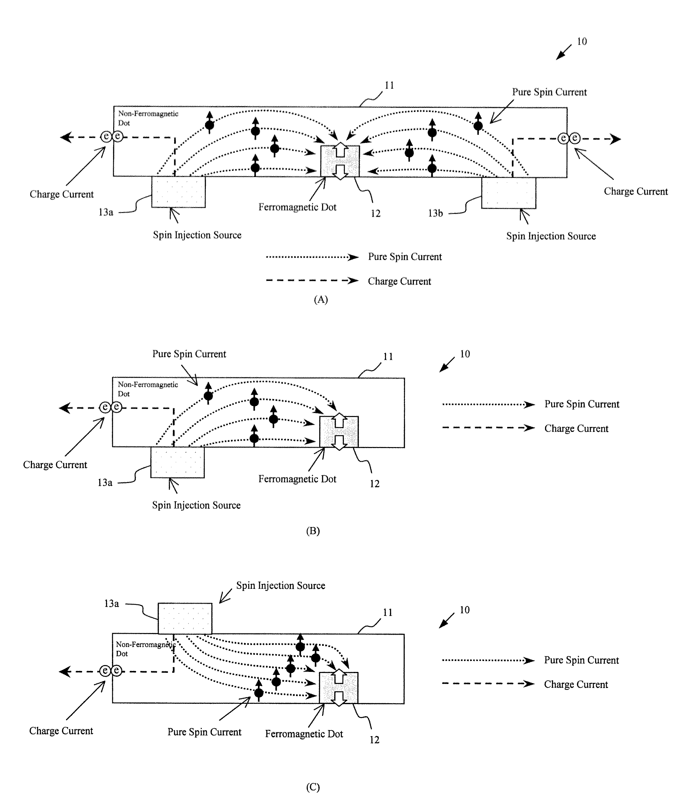
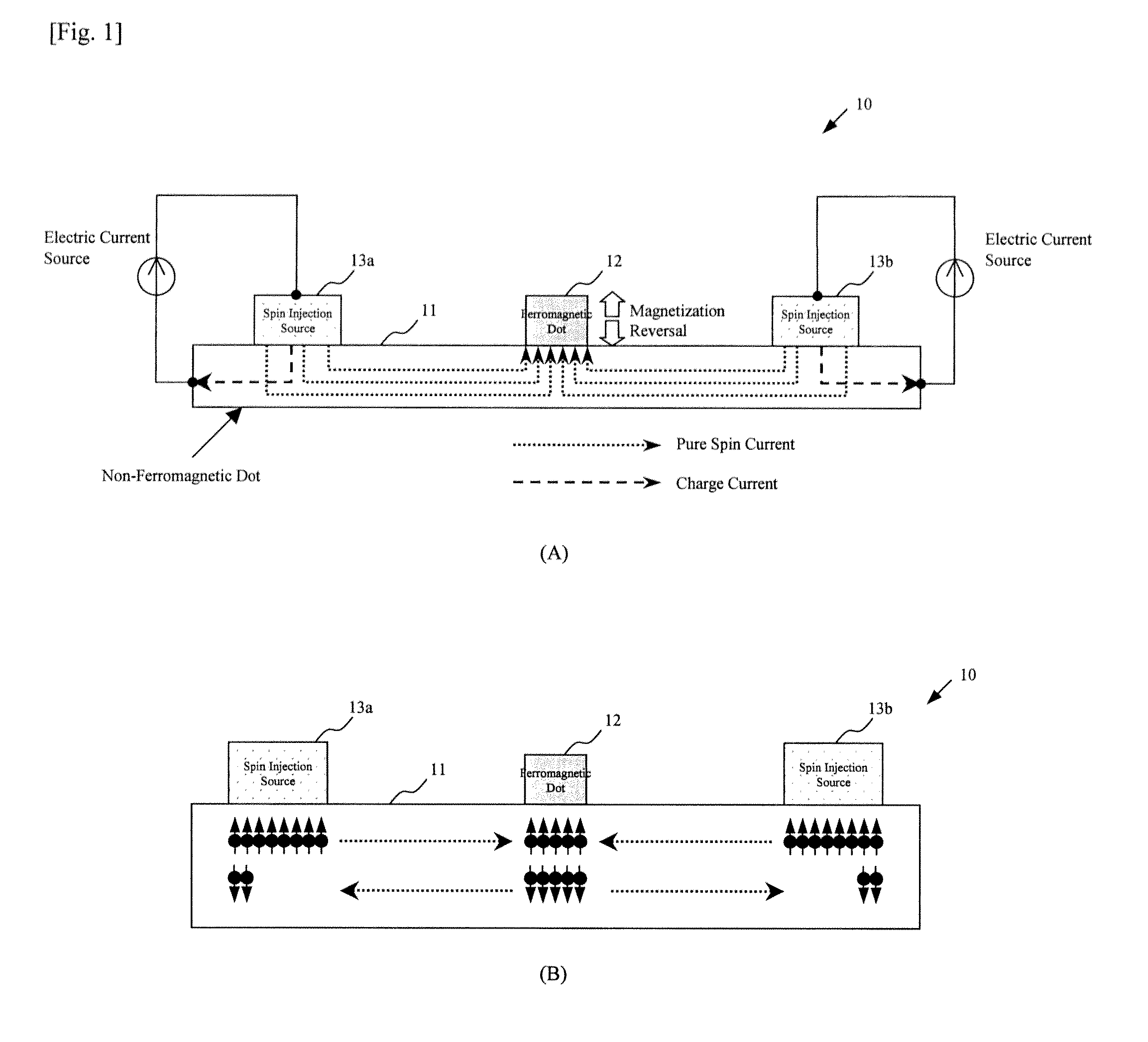
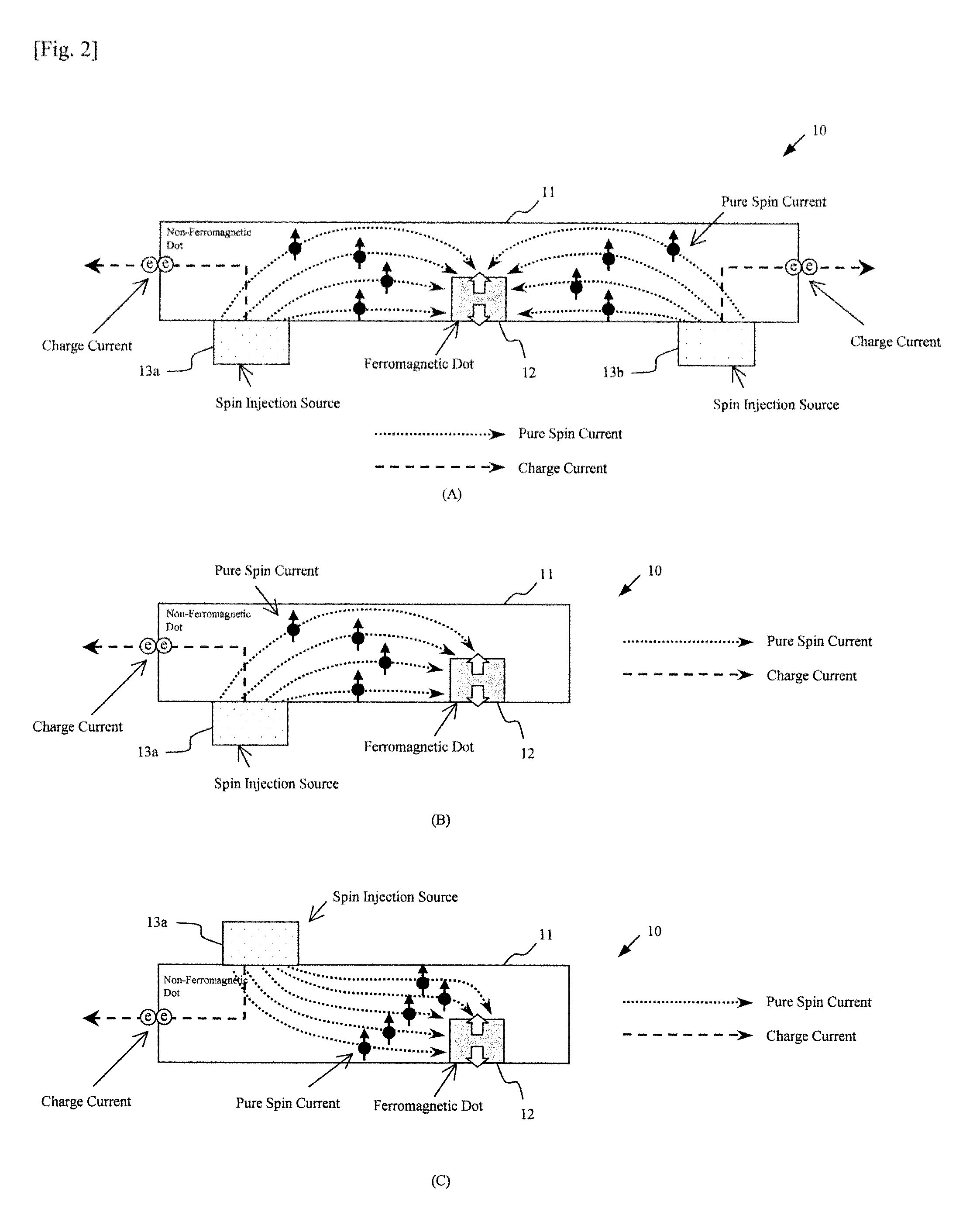
[0078]With reference to FIGS. 1 and 2, a magnetization reversal device according to this embodiment will now be explained. FIG. 1 is a first compositional view of the magnetization reversal device according to this embodiment, and FIG. 2 is a second compositional view of the magnetization reversal device according to this embodiment.

[0079]In FIG. 1(A), the magnetization reversal device 10 includes an interconnection composed of a non-ferromagnetic dot 11 (for example, copper, aluminum or the like), a ferromagnetic dot 12 (for example, permalloy, cobalt or the like) which is in contact with the interconnection of the non-ferromagnetic dot 11 at a lower face thereof, and two spin injection sources 13a and 13b (for example, permalloy, cobalt or the like) which are in contact with the interconnection of the non-ferromagnetic dot 11 at respective lower faces thereof. The ferromagnetic dot 12 is arranged between the spin injection sources 13a and 13b. Each of the spin inje...

second embodiment

of the Invention

[0089]With reference to FIGS. 3 and 4, a memory element according to this embodiment will now be explained. FIG. 3 is a first plan view of the memory element according to this embodiment, and a cross-sectional view of the first plan view. FIG. 4 is a second plan view of the memory element according to this embodiment, and a cross-sectional view of the second plan view.

[0090]In FIG. 3(A), the memory element 30 includes an interconnection composed of a non-ferromagnetic dot 11 which is formed into a matrix-like configuration, an interconnection composed of a conductor body 31 for supplying an electric current, a ferromagnetic dot 12 placed at a point of intersection in the interconnection of the non-ferromagnetic dot 11, and spin injection sources 13a, . . . , and 13d placed at points at which the interconnection of the non-magnetic body 11 and the interconnection of the conductor body 31 are intersected with each other in the vicinity of the point of interconnection a...

third embodiment

of the Invention

[0099]With reference to FIGS. 5 to 7, a magnetic field generation device according to this embodiment will now be explained. FIG. 5 is a first whole perspective view of the magnetic field generation device according to this embodiment, and a cross-sectional view thereof.

[0100]As shown in the aforesaid first and second embodiments, it is possible to carry out of a control of a magnetization direction of a ferromagnetic dot with pure spin currents by controlling electric currents. Also, by injecting the spin currents which are in parallel with the magnetization direction, a ferromagnetic coupling effect based on a spin torque is obtained so that the magnetization direction in a fine ferromagnetic dot can be strongly fixed in a direction of the injected spins.

[0101]Therefore, in this embodiment, reference is made to the magnetic field generation device which is applicable to a magnetic head or the like wherein a magnetic field, which is generated at a tip end of a fine ...


PUM


Abstract

A magnetization reversal device includes a ferromagnetic 12 body which is provided in an interconnection of a non-ferromagnetic dot 11 so that a part or a whole of the ferromagnetic dot is three-dimensionally buried in the interconnection of said non-ferromagnetic dot, and a spin injection source 13 which generates a spin-polarized pure spin current without a flow of charges, and which is provided in the interconnection of the non-ferromagnetic dot 11 to be in contact therewith so that the interconnection of the non-ferromagnetic dot serves as a common electrode, and the pure spin current flows into the ferromagnetic dot 2 through the interconnection of the non-magnetic body by the spin injection source 13 due to a diffusion current, to thereby reverse magnetization of the ferromagnetic dot 12. By injecting the pure spin current, using this planar structure, it is possible to easily carry out the magnetization reversal of the ferromagnetic dot 12 even if it is a thick film ferromagnetic dot without being subjected to limitation of a spin diffusion length.

Description

TECHNICAL FIELD[0001]The present invention relates to a magnetization reversal technique based on a spin injection.BACKGROUND OF ART[0002]In late years, although miniaturization of CMOS transistors advance, it is concerned about the miniaturization being near to the limit. Therefore, before the limit of the miniaturization of the CMOS transistors can be defeated, it is necessary to develop a new feature element based on a different operation principle.[0003]A magnetoresistive RAM (MRAM) having a magneto tunnel junction (MTJ) as a basic structure (see: Non-Patent Documents 1 and 2) is a high performance energy-saving element utilizing a non-volatility of a ferromagnetic dot, and research and development for a practical use are carried out as one of major candidates of next-generation electronic devices (see: Non-Patent Document 3).[0004]A magneto tunnel junction (MTJ) element, which is an important component of the MRAM, realizes a large magnetoresistance variation (TMR ratio) of sev...

Claims


Application Information

Patent Timeline
IPC IPC(8): H01L29/82
CPCG11C11/16H01L43/08H01L27/22G11C11/1675G11C11/1659G11C11/161G11C11/1653H10B61/00H10N59/00H10N50/10H10N50/01
Inventor KIMURA, TAKASHIHAMAYA, KOHEI
Owner KYUSHU UNIV
Why Eureka
Try Eureka