Character parameters obtaining method for displacement control mechanism of hydraulic pump and detecting device for carrying out the method

a technology of displacement control mechanism and characteristic parameter, which is applied in the direction of positive displacement liquid engine, machine/engine, servomotor, etc., can solve the problems of poor real-time performance of flow rate measurement by flow meters, poor performance of performance analysis, and poor performance of hydraulic pump output flow ra

Inactive Publication Date: 2012-05-31
HUNAN SANY INTELLIGENT CONTROL EQUIP +1
View PDF7 Cites 8 Cited by
  • Summary
  • Abstract
  • Description
  • Claims
  • Application Information

AI Technical Summary

Benefits of technology

[0016]Therefore, a basic objective of the present disclosure is to provide a method for evaluating the performance of a displacement control mechanism. The method evaluates the characteristics o...

Problems solved by technology

If, as the pressure varies, the output power of the hydraulic pump remains substantially unchanged, then the performance of the displacement control mechanism is considered good; otherwise, the performance is considered bad.
However, the measurement of the output flow rate of the hydraulic pump is not satisfactory.
Flow rate measurement by flow meters has a poor real-time performance and a long response time, normally tens or even hundreds of times longer than the response time of a pressure measuring device, which degrades the reliability of the obtained output flow rate parameter.
Moreover, control precision of flow meters is far from satisfactory in measuring the displacement control mechanism, with a measurement error many times larger than pressure measuring devices.
Therefore, the measurement of the output flow rate of a hydra...

Method used


Image

  • Character parameters obtaining method for displacement control mechanism of hydraulic pump and detecting device for carrying out the method
  • Character parameters obtaining method for displacement control mechanism of hydraulic pump and detecting device for carrying out the method
  • Character parameters obtaining method for displacement control mechanism of hydraulic pump and detecting device for carrying out the method

Examples


first embodiment

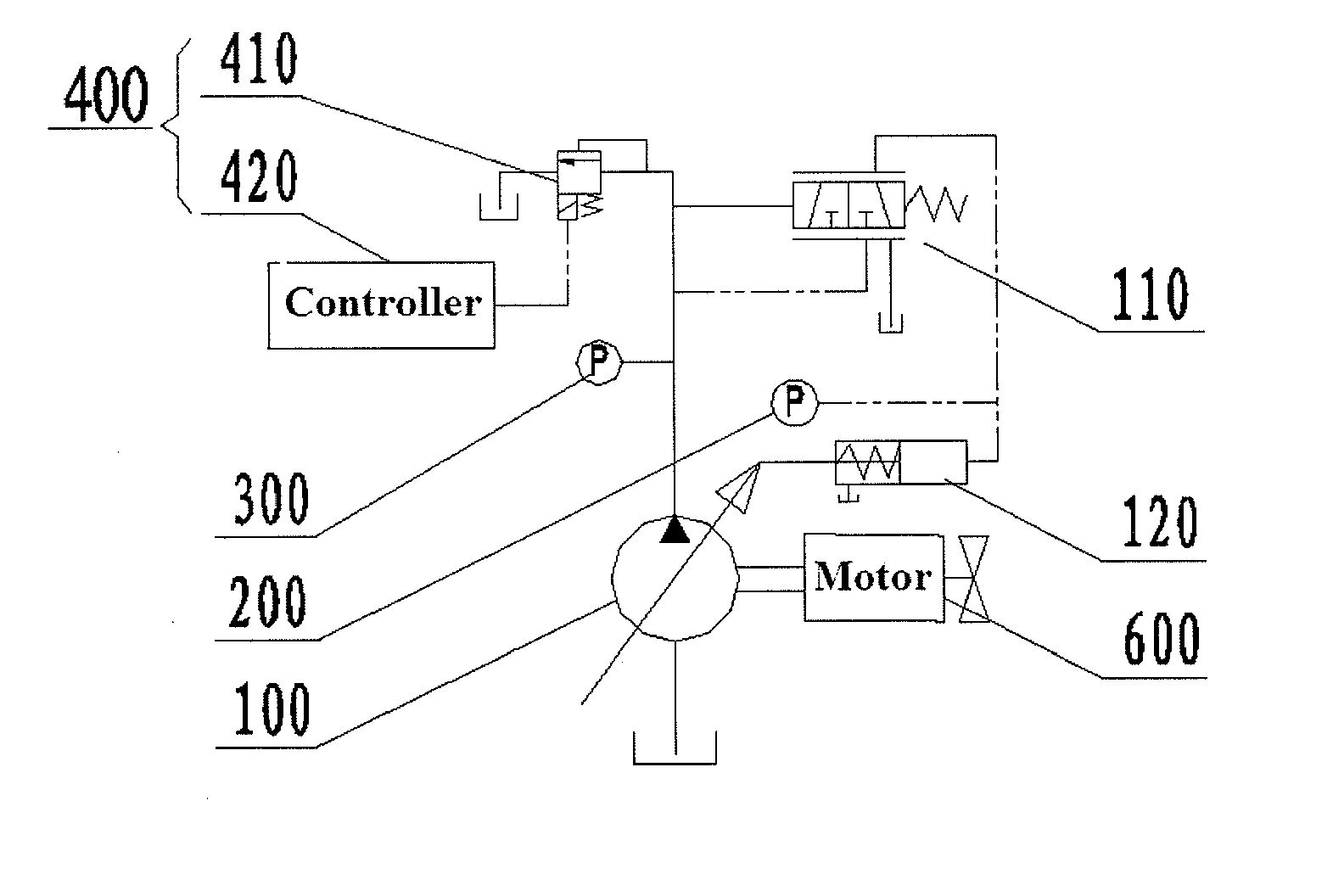
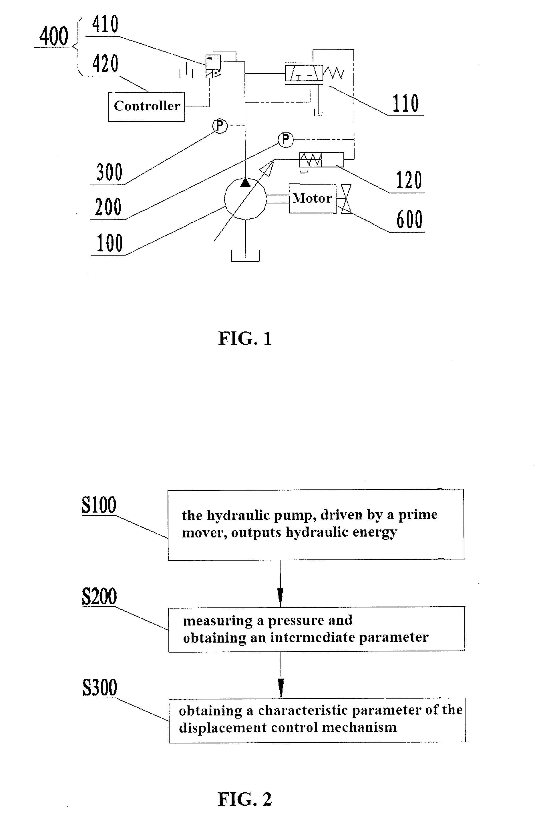
[0045]Now refer to FIG. 1, which illustrates the principle of a measuring device for a displacement control mechanism for a hydraulic pump according to the present disclosure.

[0046]The measuring device for a displacement control mechanism for a hydraulic pump according to the first embodiment includes: a prime mover 600, a loading device 400, a first pressure measuring device 200 and a second pressure measuring device 300. FIG. 1 also shows a hydraulic pump 100 to be measured, and the hydraulic pump 100 has a displacement control mechanism 110 and a variable displacement mechanism 120. The displacement control mechanism 110 has an input connected with an outlet of the hydraulic pump, and an output connected with the variable displacement mechanism 120. The prime mover 600 is used to drive the hydraulic pump 100. The loading device 400 is connected with the outlet of the hydraulic pump, forming the load of the hydraulic pump 100. The first pressure measuring device 200 and the second...

second embodiment

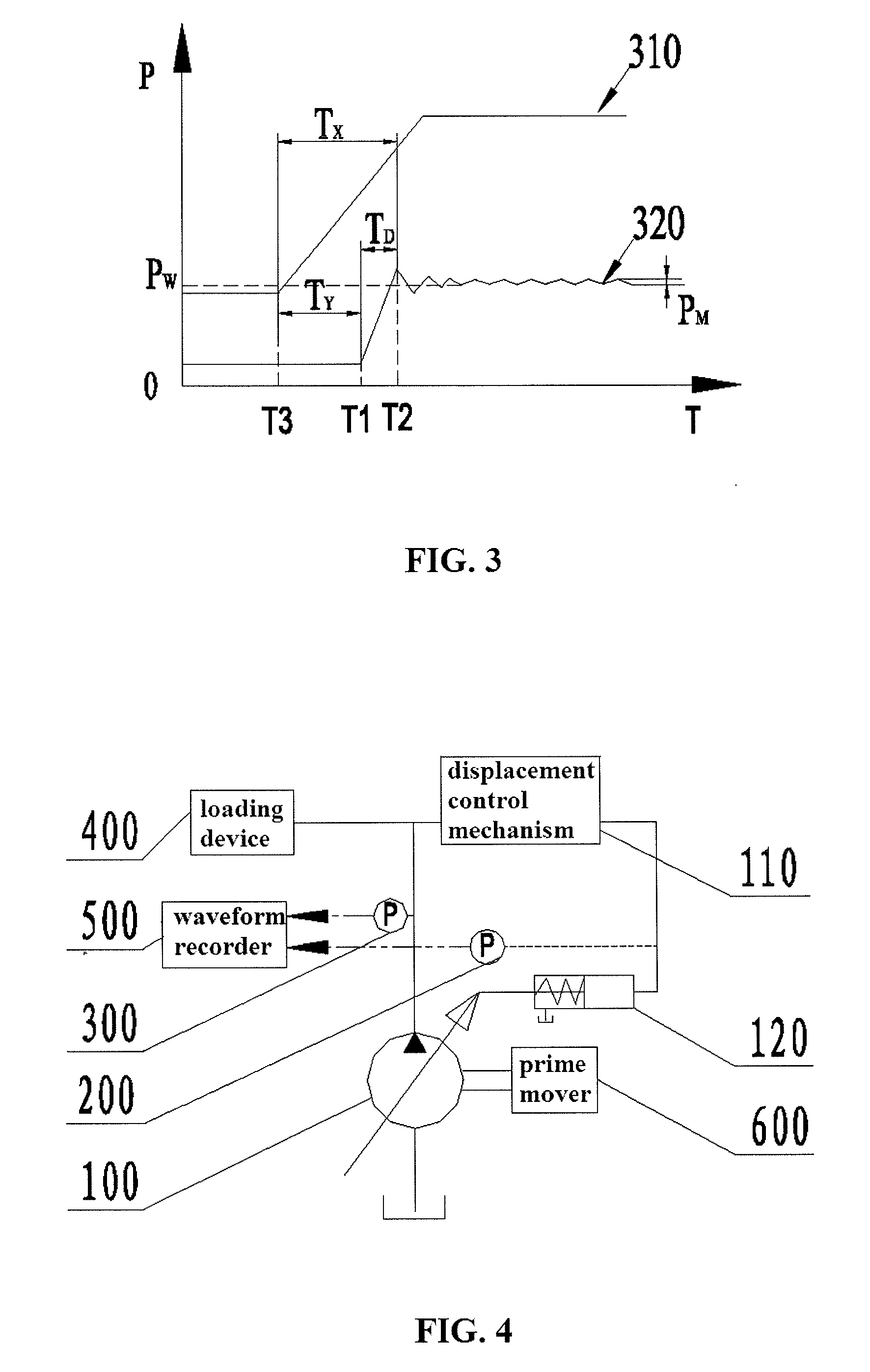
[0056]To obtain the intermediate parameter and the characteristic parameter of the displacement control mechanism 110 more conveniently, an appropriate waveform recorder can be used to receive pressure signals output by the pressure measuring devices, and to perform predetermined processing of the pressure signals. Now refer to FIG. 4, which illustrates the principle of a measuring device for a displacement control mechanism for a hydraulic pump according to the present disclosure.

[0057]The measuring device for a displacement control mechanism for a hydraulic pump according to the second embodiment of the present disclosure includes: a prime mover 600, a loading device 400, a first pressure measuring device 200 and a second pressure measuring device 300. In addition, comparing with the first embodiment, a waveform recorder 500 is added, and pressure sensors are used as the first measuring device 200 and the second measuring device 300. The waveform recorder 500 is connected with the...

third embodiment

[0064]In some cases, the predetermined intermediate parameter can be obtained by using only one pressure measuring device. Now refer to FIG. 6, which illustrates the principle of a measuring device for a displacement control mechanism for a hydraulic pump according to the present disclosure.

[0065]The measuring device for a displacement control mechanism for a hydraulic pump according to the third embodiment of the present disclosure includes: a prime mover 600, a loading device 400, a waveform recorder 500, and a first pressure measuring device 200. In this embodiment, the measuring device for a displacement control mechanism for a hydraulic pump includes the first pressure measuring device 200 only, and the other structures are the same as the measuring device for a displacement control mechanism for a hydraulic pump according to the second embodiment. Therefore, according to the pressure signal output by the first pressure measuring device 200, the waveform recorder 500 can only g...


PUM


Abstract

A character parameters obtaining method for a displacement control mechanism of a hydraulic pump and a detecting device for carrying out the method are disclosed. The method involves constructing a hydraulic system; outputting hydraulic energy by the hydraulic pump driven by a primary motor; detecting pressure of a displacement control mechanism; obtaining middle parameters by obtaining the time required for preset change of the pressure at the output end of the displacement control mechanism; obtaining character parameters of the displacement control mechanism according to the middle parameters. The method can obtain the character parameters of the displacement control mechanism by the pressure detection, so that the performance of the displacement control mechanism can be judged according to the obtained character parameters. The method avoids the need of obtaining the output flow of the hydraulic pump so as to eliminate the problem caused by using a flow meter or using an obliquity sensor to obtain the character parameters.

Description

CROSS-REFERENCE TO RELATED APPLICATION[0001]This application claims the benefit of Chinese patent application NO. 200910158808.1, titled “Method for obtaining characteristic parameter of displacement control mechanism for hydraulic pump and measuring device thereof” and filed with the State Intellectual Property Office on Jul. 6, 2009, which is hereby incorporated by reference in its entirety.FIELD OF THE INVENTION[0002]The present disclosure relates to hydraulic measurement technology, and particularly to a method for obtaining a characteristic parameter of a displacement control mechanism for a hydraulic pump, the displacement control mechanism being used to adjust and control the displacement of the hydraulic pump; and to a measuring device for the displacement control mechanism for the hydraulic pump which implements the method.BACKGROUND OF THE INVENTION[0003]Generally, engineering machines are characterized by large transmit power, slow movement, wide speed range and complex c...

Claims


Application Information

Patent Timeline
IPC IPC(8): F04B49/08
CPCF04B49/002F04B49/08F04B2205/04F15B11/055F15B19/002F15B2211/6652F15B2211/25F15B2211/6309F15B2211/6316F15B2211/6323F15B2211/6333F15B2211/20553
Inventor ZHOU, XIANGCAO, XIANLI
Owner HUNAN SANY INTELLIGENT CONTROL EQUIP
Why Eureka
Try Eureka