
Functionally gradient inorganic resist, substrate with functionally gradient inorganic resist, cylindrical base material with functionally gradient inorganic resist, method for forming functionally gradient inorganic resist and method for forming fine pattern, and inorganic resist and method for forming the same

a technology of inorganic resist and functional gradient, which is applied in the direction of photosensitive materials, instruments, photomechanical apparatuses, etc., can solve the problems of low production yield, achieve high production efficiency, improve resist resolution at the time of thermal lithography using focused laser beam, and achieve low cost

Inactive Publication Date: 2012-05-31
HOYA CORP
View PDF16 Cites 5 Cited by
  • Summary
  • Abstract
  • Description
  • Claims
  • Application Information

AI Technical Summary

Benefits of technology

[0038]Further, a two-photon light absorption process is described as a method for forming a pattern other than the semiconductor lithography. This process is a technique of causing a non-linear phenomenon caused by two-photon excitation by simultaneously absorbing two-photons, and the same effect is obtained as the effect at the time of absorbing one photon having a half-wavelength. Namely, ½ of a use wavelength is a resolution limit, to thereby achieve a finer pattern.
[0055]Regarding formation of the fine pattern in a large area at a low cost, it can also be considered that a roll nano imprint method is used, which is a method of transferring a pattern on the surface of the mold to a workpiece, by bringing a cylindrical roller mold into rolling contact with the surface of the workpiece.
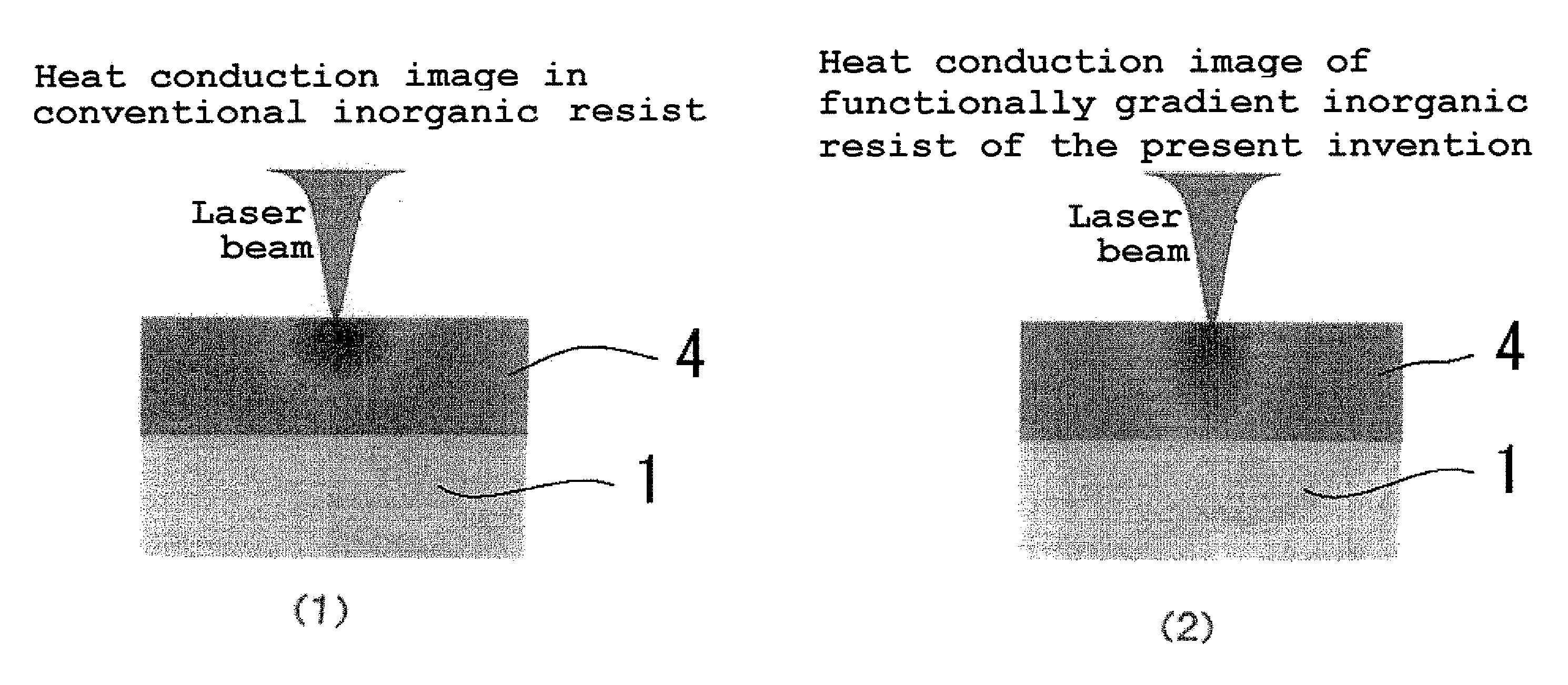
[0059]An object of the present invention is to improve the resolution of the resist in case of the thermal lithography using a focused laser, thus making it possible to form a fine pattern in a large area at a low cost.Means for Solving the Problem
[0113]According to the present invention, resist resolution at the time of thermal lithography using focused laser beam can be improved, and a fine pattern can be formed in a large area at a low cost.

Problems solved by technology

Further, a wire grid type polarizer (polarizing plate) has been proposed as an alternative method for an optical polarizer (polarizing plate) based on a stretching method that has low production yield.

Method used


Image

  • Functionally gradient inorganic resist, substrate with functionally gradient inorganic resist, cylindrical base material with functionally gradient inorganic resist, method for forming functionally gradient inorganic resist and method for forming fine pattern, and inorganic resist and method for forming the same
  • Functionally gradient inorganic resist, substrate with functionally gradient inorganic resist, cylindrical base material with functionally gradient inorganic resist, method for forming functionally gradient inorganic resist and method for forming fine pattern, and inorganic resist and method for forming the same
  • Functionally gradient inorganic resist, substrate with functionally gradient inorganic resist, cylindrical base material with functionally gradient inorganic resist, method for forming functionally gradient inorganic resist and method for forming fine pattern, and inorganic resist and method for forming the same

Examples


embodiment 1

[0156]An embodiment of the present invention will be described hereafter.

[0157]The embodiment of the present invention will be described in the following order.

1. Outline of the functionally gradient inorganic resist

2. Details of the functionally gradient inorganic resist

[0158]1) Composition

[0159]2) Resist resolution characteristic value

[0160]i) Prediction of resist composition for the present invention from the correlation of a resist resolution characteristic and resist composition

[0161]ii) Resist sensitivity

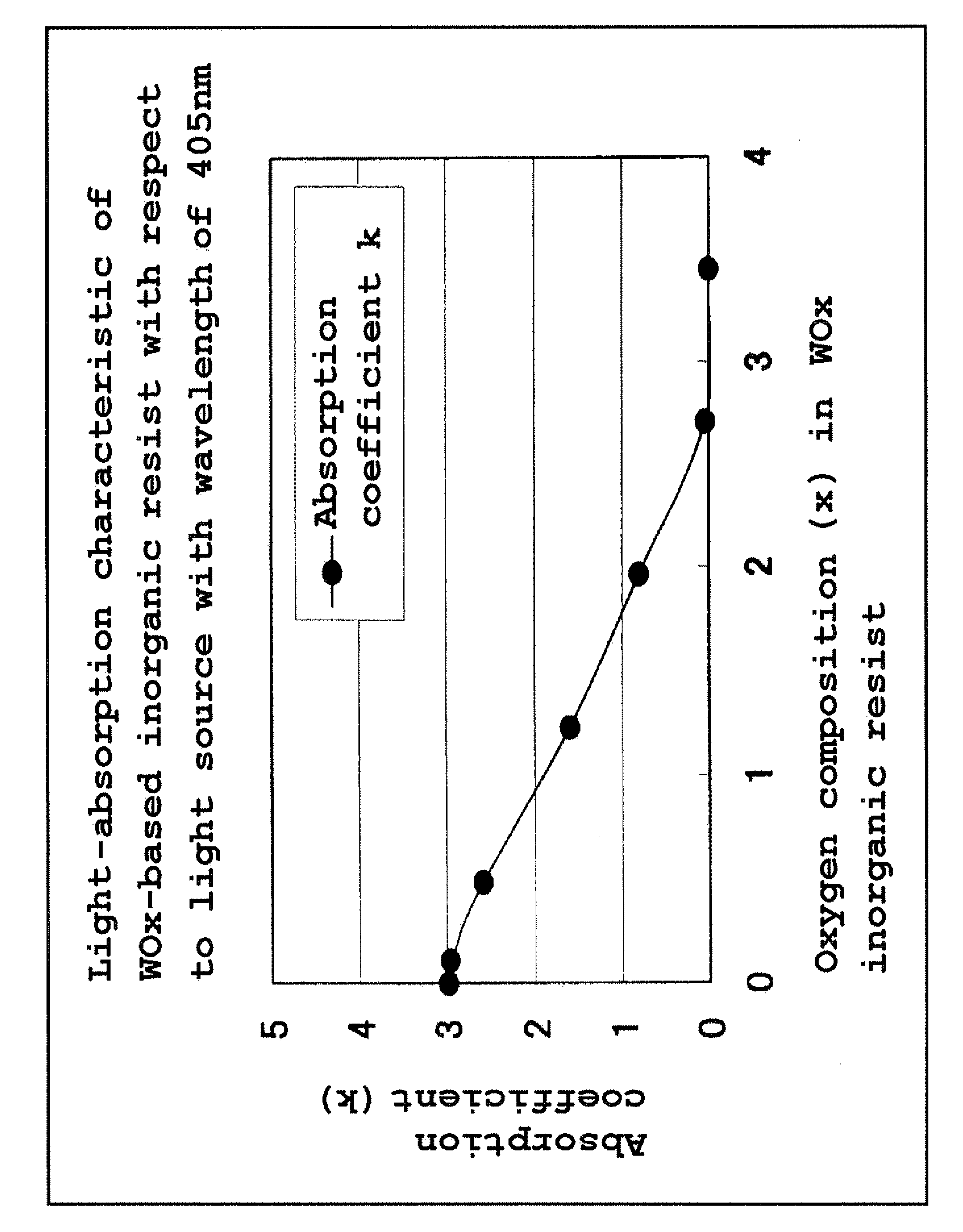
[0162]iii) Optical characteristic (optical-absorption coefficient)

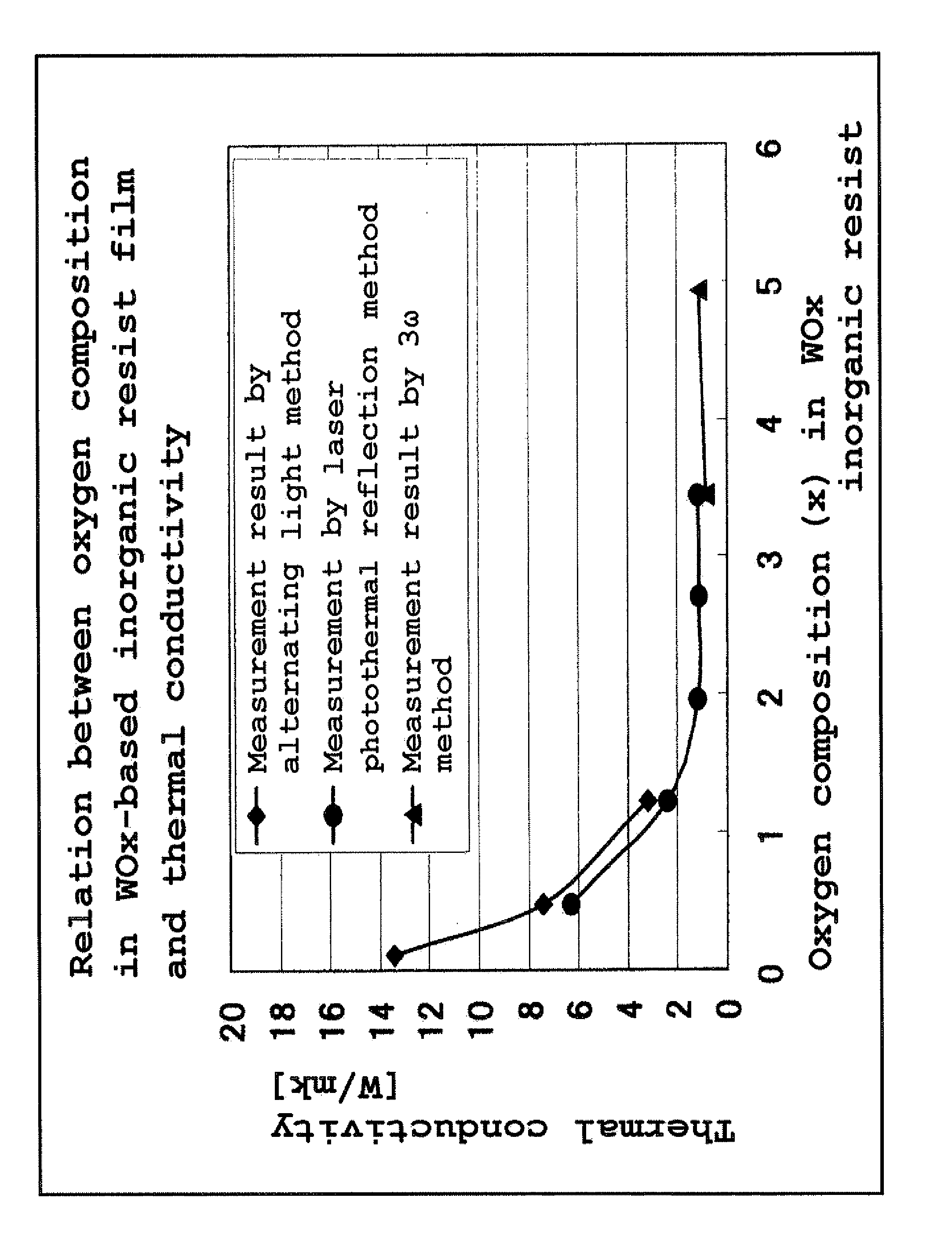
[0163]iv) Thermal characteristic (thermal conductivity)

[0164]3) Film thickness

[0165]4) Structure

3. Outline of a substrate with functionally gradient inorganic resist

4. Details of a substrate with functionally gradient inorganic resist

[0166]1) Substrate (base material)

[0167]2) Ground layer

[0168]3) Etching mask layer

[0169]4) Inorganic resist

5. A method for manufacturing the substrate with functionally gradient ino...

second embodiment

[0342]A technical range of the present invention is not limited to the aforementioned embodiment, and includes various modifications and improvements within a range capable of deriving a specific effect obtained by constituting features of the present invention and a combination thereof.

[0343]Modified examples of the embodiment 1 will be described hereafter in detail. Note that in the embodiments described hereafter, a portion not particularly specified is the same as that of the embodiment 1.

[0344]In this embodiment, the functionally gradient resist material comprises a first material composed of at least one of suboxide, nitride, or suboxinitride of Ti, V, Cr, Mn, Cu, Zn, Ge, Se, Y, Zr, Nb, Mo, Tc, Ru, Rh, Pd, Ag, Sb, Te, Hf, Ta, W, Re, Ir, Pt, Au, and Bi, and a second material composed of at least one of the above elements excluding the first material.

[0345]Then, compositions of the first material and the second material are relatively and continuously varied from the main surfac...

embodiment 3

[0349]Although the substrate 1 is used in the embodiment 1, in this embodiment, explanation will be given for a case that a cylinder-shaped base material (also called a cylindrical base material hereafter) is used instead of the substrate 1.

[0350]In this embodiment, the ground layer 2 is formed on the surface of the cylindrical base material, and the functionally gradient inorganic resist 4 is formed on the ground layer 2. Then, the cylindrical base material with resist is precisely set on the rotary stage of the laser drawing device. Subsequently, drawing or exposure and development are implemented on the inorganic resist 4 so as to be patterned into a desired shape, by the thermal lithography using the focused laser beams having an automatic focusing function, while rotating the cylindrical base material with resist. Then, the resist pattern 5 is transferred to the ground layer 2 by etching, and the pattern of the ground layer 2 is formed on the cylindrical base material.

[0351]Fur...


PUM


Abstract

A functionally gradient inorganic resist that changes in its state by heat, having a main surface irradiated with laser beams and a rear surface opposed to the main surface; the functionally gradient inorganic resist including a single layer resist, wherein at least a composition of the single layer resist is continuously varied from the main surface side to the rear surface side, and anisotropy of an area in which a temperature reaches a fixed temperature when being irradiated with laser beams locally, is continuously increased from the main surface side to the rear surface side in the single layer resist.

Description

TECHNICAL FIELD[0001]The present invention relates to a functionally gradient inorganic resist, a substrate with a functionally gradient inorganic resist, a cylindrical base material with a functionally gradient inorganic resist, a method for forming the functionally gradient inorganic resist and a method for forming a fine pattern thereon, and an inorganic resist and a method for manufacturing the same, and particularly relates to a functionally gradient inorganic resist on which a fine pattern is formed and which is made of a high resolution thermo-sensitive material, and a high precision nano-imprint mold using the same.DESCRIPTION OF RELATED ART[0002]In recent years, applications requiring fine patterning of 100 nm or less, have been developed.[0003]For example, in a magnetic recording field, as a next generation system of a perpendicular recording system, a technique called a discrete track media technique, namely a technique of forming a non-magnetic groove with a width of 30 ...

Claims


Application Information

Patent Timeline
IPC IPC(8): G03F7/20G03F7/075G03F7/004
CPCG03F7/2053G03F7/0042G03F7/0041G03F7/0045G03F7/11H01L21/0271H01L21/3065
Inventor AMEMIYA, ISAONAKATSUKA, SAKAETANIGUCHI, KAZUTAKEKIMURA, IKURU
Owner HOYA CORP
Learn More