Method of forming a solid state cathode for high energy density secondary batteries

a secondary battery and solid state cathode technology, applied in the field of apparatus and methods for chemically depositing solid state cathode films for alkali ion batteries, can solve the problems of cumbersome use of powder and traditional methods of making powder to make film, unnecessarily lowering the power density of batteries containing, etc., to achieve high energy density and improve solid state lithium batteries

Active Publication Date: 2012-06-07
QUANTUMSCAPE BATTERY INC
View PDF2 Cites 20 Cited by
  • Summary
  • Abstract
  • Description
  • Claims
  • Application Information

AI Technical Summary

Benefits of technology

[0017]Objects of the present invention include the following: providing a method for making a solid state cathode having high energy density; providing a method for making a solid state cathode by depositing a precursor mixture that may be heat treated to create a final cathode composition; providing a method for assembling an all solid state lithium battery; providing an improved solid state alkali ion battery; and, providing a manufacturing friendly and an improved solid state lithium battery. These and other objects and advantages of the invention will become apparent from consideration of the following specification, read in conjunctio

Problems solved by technology

Over the years these cathodes were fabricated by a series of complex and expensive techniques.
The inert binder content in these cathodes could be as high as 30% and unnecessarily lowers the power density of batteries containing them.
It is therefore clear that traditional methods of making the powder and deploying the powder to make the film are cumbersome, and more streamlined methods are needed to enable wider adoption of lithium ion batteries.
These processes are slow

Method used


Image

  • Method of forming a solid state cathode for high energy density secondary batteries
  • Method of forming a solid state cathode for high energy density secondary batteries
  • Method of forming a solid state cathode for high energy density secondary batteries

Examples


example

[0086]The cathodes made in the foregoing examples on the current collector then become substrates for the fabrication of either of the following cell types:[0087](a) All solid state battery cells. Here, the solid state electrolyte is deposited by VPSPEED, or vacuum sputtering, or any other methods on the cathode; followed by lithium metal deposition as anode, then TiN / Cu or stainless steel as the anode current collector to complete the cell. Other kinds of anodes such as SnO, or Si deposited on Cu substrate can also be glued to the cathode / electrolyte substrate using lithium ion conducting glue to complete the cell.[0088](b) Liquid electrolyte battery cells. Here, the grown cathode, a polymer separator, and an anode are assembled in a container or pouch with appropriate leads attached to the current collectors. The container or pouch is then filled with the liquid electrolyte and sealed to complete the cell.

[0089]For simplicity, the foregoing examples depict a single substrate of so...


PUM

PropertyMeasurementUnit
Temperatureaaaaaaaaaa

Abstract

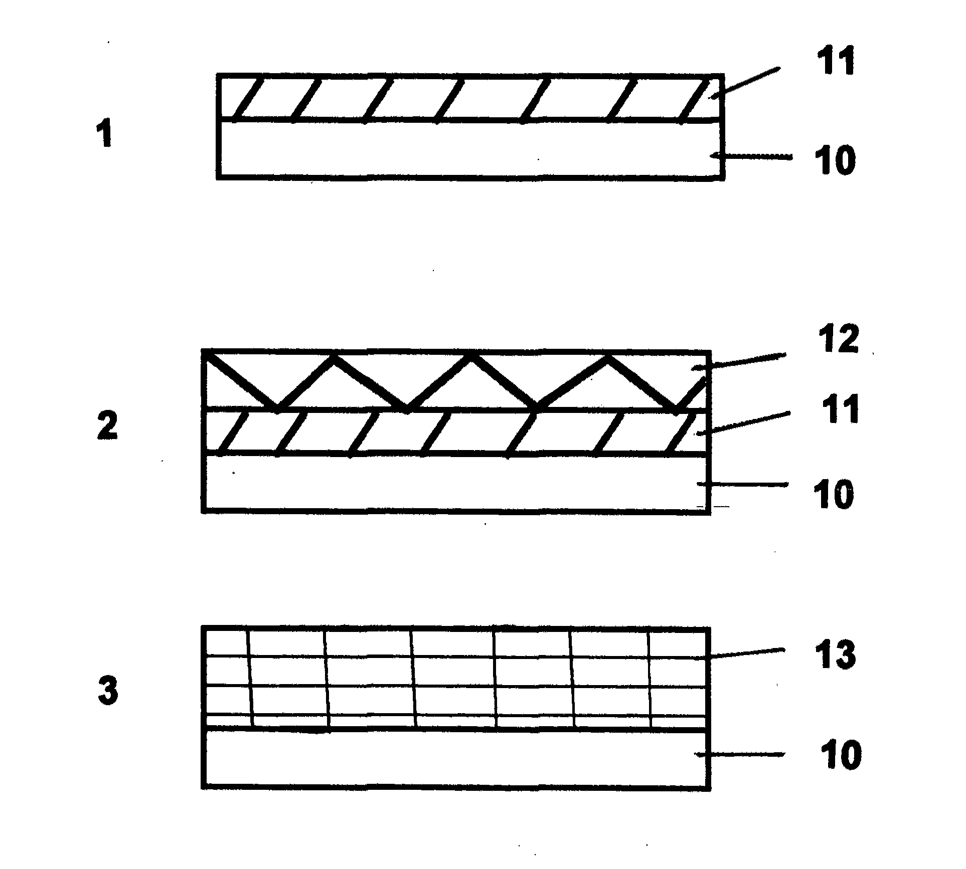
A method for making a solid state cathode comprises the following steps: forming an alkali free first solution comprising at least one transition metal and at least two ligands; spraying this solution onto a substrate that is heated to about 100 to 400° C. to form a first solid film containing the transition metal(s) on the substrate; forming a second solution comprising at least one alkali metal, at least one transition metal, and at least two ligands; spraying the second solution onto the first solid film on the substrate that is heated to about 100 to 400° C. to form a second solid film containing the alkali metal and at least one transition metal; and, heating to about 300 to 1000° C. in a selected atmosphere to react the first and second films to form a homogeneous cathode film. The cathode may be incorporated into a lithium or sodium ion battery.

Description

CROSS-REFERENCE TO RELATED APPLICATIONS[0001]This application is related to U.S. patent application Ser. Nos. 12 / 151,562 filed on May 7, 2008, now U.S. Pat. No. 7,700,161, entitled “Film Growth System and Method,” Ser. No. 12 / 151,465, filed on May 7, 2008, entitled “Zinc Oxide Film and Method of Making,” Ser. No. 12 / 462,146, filed on Jul. 30, 2009, entitled “Method for Fabricating Cu-Containing Ternary and Quaternary Chalcogenide Thin Films,” Ser. No. 12 / 798,519, filed on Apr. 6, 2010, entitled, “Apparatus and Method for Depositing Alkali Metals,” Ser. No. 12 / 798,515, filed on Apr. 6, 2010, entitled “Method of Forming Solid State Electrolyte Having High Lithium Ion Conduction and Battery Incorporating Same,” and Ser. No. 12 / 798,510, filed on Apr. 6, 2010, entitled “Solid State Electrolytes Having High Li Ion Conduction”, all by the present inventor, the entire disclosures of which are incorporated herein by reference.BACKGROUND OF THE INVENTION[0002]1. Field of the Invention[0003]Th...

Claims


Application Information

Patent Timeline
IPC IPC(8): H01M10/26B05D5/12
CPCH01M4/0404Y10T29/49108H01M4/0435H01M4/0471H01M4/049H01M4/1391H01M4/625H01M10/052H01M10/0525H01M10/054H01M10/0562H01M10/0566Y02E60/122H01M10/26H01M10/28H01M10/058Y10T29/49115H01M4/0419Y02E60/10Y02P70/50
Inventor OLADEJI, ISAIAH O.
Owner QUANTUMSCAPE BATTERY INC
Why Eureka
Try Eureka