Gas flow guiding device for use in crystal-growing furnace

a technology of crystal growth furnace and guiding device, which is applied in the direction of polycrystalline material growth, crystal growth process, coating, etc., can solve the problems of reducing crystal quality, generating a tremendous amount of electrons, and potential difference at the p-n junction, so as to reduce the concentration of impurities, improve the quality of crystal ingot, and effectively reduce the impurities present in crystal ingot.

Inactive Publication Date: 2012-06-07
NAT CENT UNIV
View PDF3 Cites 7 Cited by
  • Summary
  • Abstract
  • Description
  • Claims
  • Application Information

AI Technical Summary

Benefits of technology

[0011]Accordingly, an object of the invention is to provide a gas flow guiding device for use in a crystal-growing furnace that is capable of improving the quality of the crystal ingot produced thereby by effectively reducing the impurities present in the crystal ingot.
[0012]In order to achieve this object, a gas flow guiding device for use in a crystal-growing furnace is provided, which comprises an insulation layer enclosing a crucible, a gas inlet mounted in the insulation layer, and a gas exit formed in the insulation layer, so that the gas inlet is allowed to introduce a gas at a predetermined flow rate to generate a gas flow passing through the hot zone and carrying the impurity away from the furnace via the gas exit. A plurality of guide plates is radially arranged around the opening of the gas inlet, so that the free surface of the melt is blown by the gas flow guided by the guide plates. As a result, the crystal ingot thus obtained exhibits a reduced concentration of impurities and an improved crystal quality.
[0013]Preferably, the gas flow guiding device according to the invention additionally comprises a height-adjusting unit coupled to the gas inlet. The height-adjusting unit allows a precise control of the height of the gas inlet in relation to either the height of crucible or the height of the free surface of the melt during an actual operation, so as to maintain the distance between the opening of the gas inlet and the free surface of the melt contained in the crucible within a predetermined range. As a result, at a given gas flow rate, the impurities can be efficiently taken away from the free surface of the melt by the gas flow.
[0014]Preferably, the gas flow guiding device according to the invention additionally comprises an angle-adjusting unit provided between the respective guide plates and the gas inlet, so that the angles of the respective guide plates are adjustable according to the actual operation conditions. As such, the speed of the gas flow can be optimized depending on the growth of the crystal ingot and the quality of the crystal ingot produced can be precisely controlled.

Problems solved by technology

The semiconductor device will generate a tremendous amount of electrons when struck by the sunlight, and the movement of the electrons results in a potential difference at the P-N junction.
As a consequence, the opening of the gas inlet 25 is located so far from the free surface of the silicon melt 11 contained in the crucible 21 (namely, the interface of the silicon melt and the gas) that the gas flow introduced through the gas inlet 25 fails to effectively carry the impurities away from the free surface and leads to an unfavorable result that the crystal ingot produced thereby has a high concentration of impurities and a reduced crystal quality.

Method used


Image

  • Gas flow guiding device for use in crystal-growing furnace
  • Gas flow guiding device for use in crystal-growing furnace
  • Gas flow guiding device for use in crystal-growing furnace

Examples


Embodiment Construction

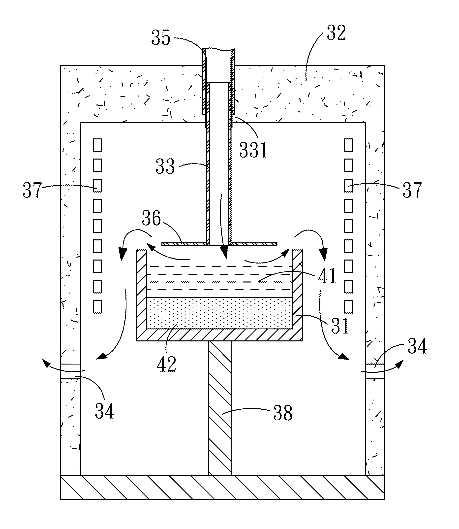
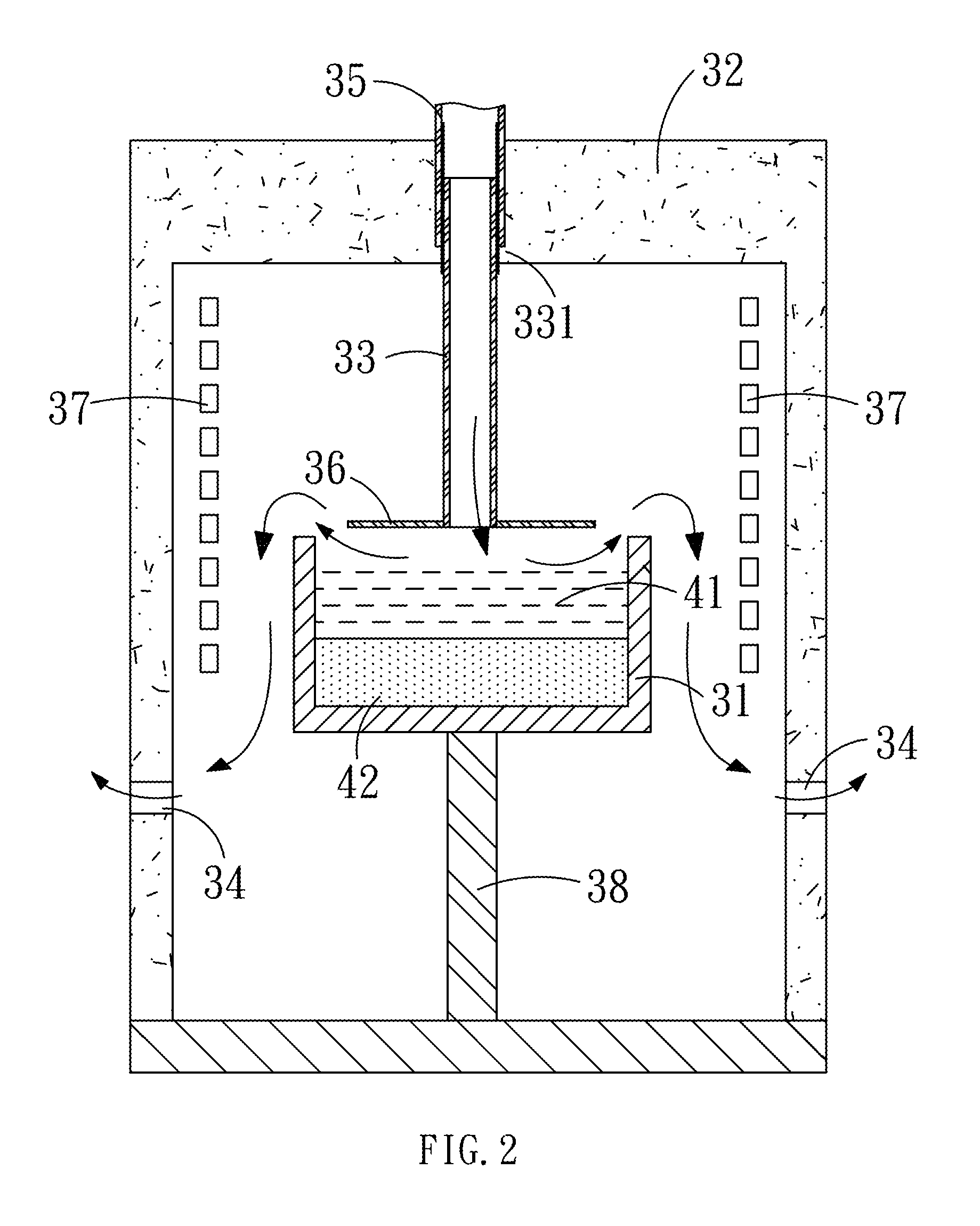
[0022]The present invention provides a gas flow guiding device for use in a crystal-growing furnace that is capable of improving the quality of the crystal ingot produced thereby by effectively reducing the impurities present in the crystal ingot. As shown in FIGS. 2 and 3, the furnace according to the invention generally comprises a crucible 31 for containing a silicon melt 41. The crucible 31 is surrounded circumferentially by an insulation layer 32, so as to constitute a hot zone, in which a heater 37 are equipped to provide heat to silicon.

[0023]The gas flow guiding device according to the invention comprises a gas inlet 33 protruding from the insulation layer 32, and a gas exit 34 formed in the insulation layer 32, so that the gas inlet 33 is allowed to introduce a gas at a predetermined flow rate to generate a gas flow passing through the hot zone and, thus, carrying the impurity away from the furnace via the gas exit 34. The gas flow guiding device is characterized by the tec...


PUM

PropertyMeasurementUnit
angleaaaaaaaaaa
angleaaaaaaaaaa
angleaaaaaaaaaa

Abstract

The present invention relates to a gas flow guiding device for use in a crystal-growing furnace. The gas flow guiding device has an insulation layer enclosing a crucible, a gas inlet mounted in the upper insulation layer, and a gas exit formed in the lateral insulation layer. A plurality of guide plates are radially arranged around the opening of the gas inlet, so that the free surface of the melt is blown by the guided gas flow in such a manner that the gas flow takes the impurity away from the free surface efficiently. As a result, the crystal ingot obtained by solidifying the melt will exhibit a reduced concentration of impurities and an improved crystal quality.

Description

BACKGROUND OF THE INVENTION[0001]1. Field of the Invention[0002]The present invention relates to a gas flow guiding device for use in a crystal-growing furnace, and more particularly, to a gas flow guiding device for use in a crystal-growing furnace that is capable of effectively reducing the impurities present in a crystal ingot produced thereby.[0003]2. Description of the Prior Art[0004]It is known in the art that a solar cell is a non-pollutant renewable energy source that can directly generate electric power by virtue of the interactions between the sunlight and chemical materials. Especially, the solar cell will not discharge any undesired waste gas during use, such as CO2, so that the solar cell is promising in helping environmental protection and solving the problem of the earth's greenhouse effect.[0005]A solar cell is a device that is capable of converting the solar energy into electrical power by generating a potential difference at the P-N junction interface of a semic...

Claims


Application Information

Patent Timeline
Patent Type & Authority Applications(United States)
IPC IPC(8): C23C16/455
CPCC30B11/006Y10T117/108C30B28/06
Inventor CHEN, JYH-CHENTENG, YING-YANGLU, CHUNG-WEICHEN, HSUEH-I
Owner NAT CENT UNIV
Why Eureka
Try Eureka